Sound damping for power tools

a power tool and sound damping technology, applied in the field of power tool sound damping, can solve the problems of lack of power, inconvenient manufacture, lack of power, etc., and achieve the effect of reducing and eliminating undesired sound and/or nois

Active Publication Date: 2020-07-21
BLACK & DECKER INC
View PDF84 Cites 336 Cited by
  • Summary
  • Abstract
  • Description
  • Claims
  • Application Information

AI Technical Summary

Benefits of technology

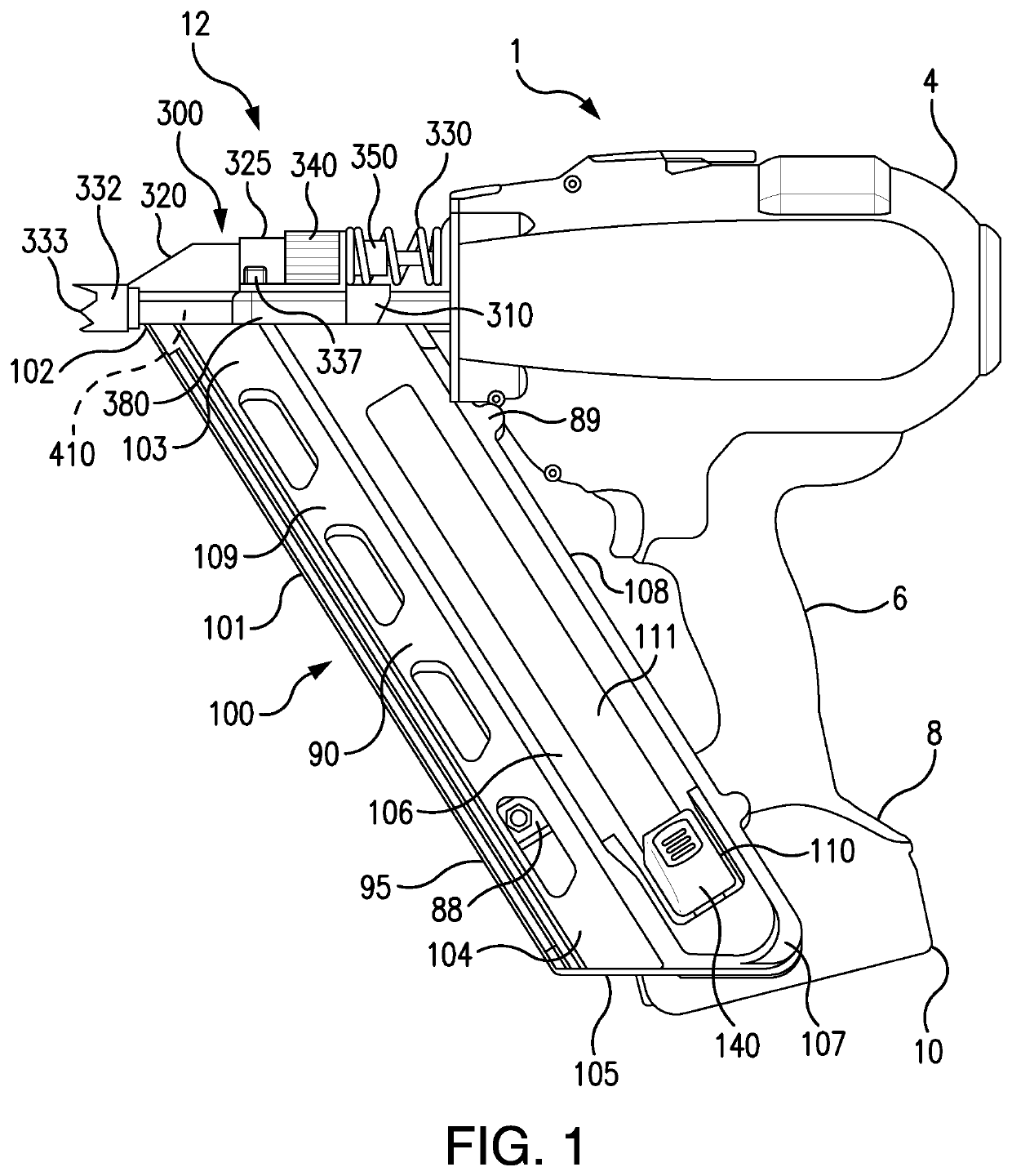
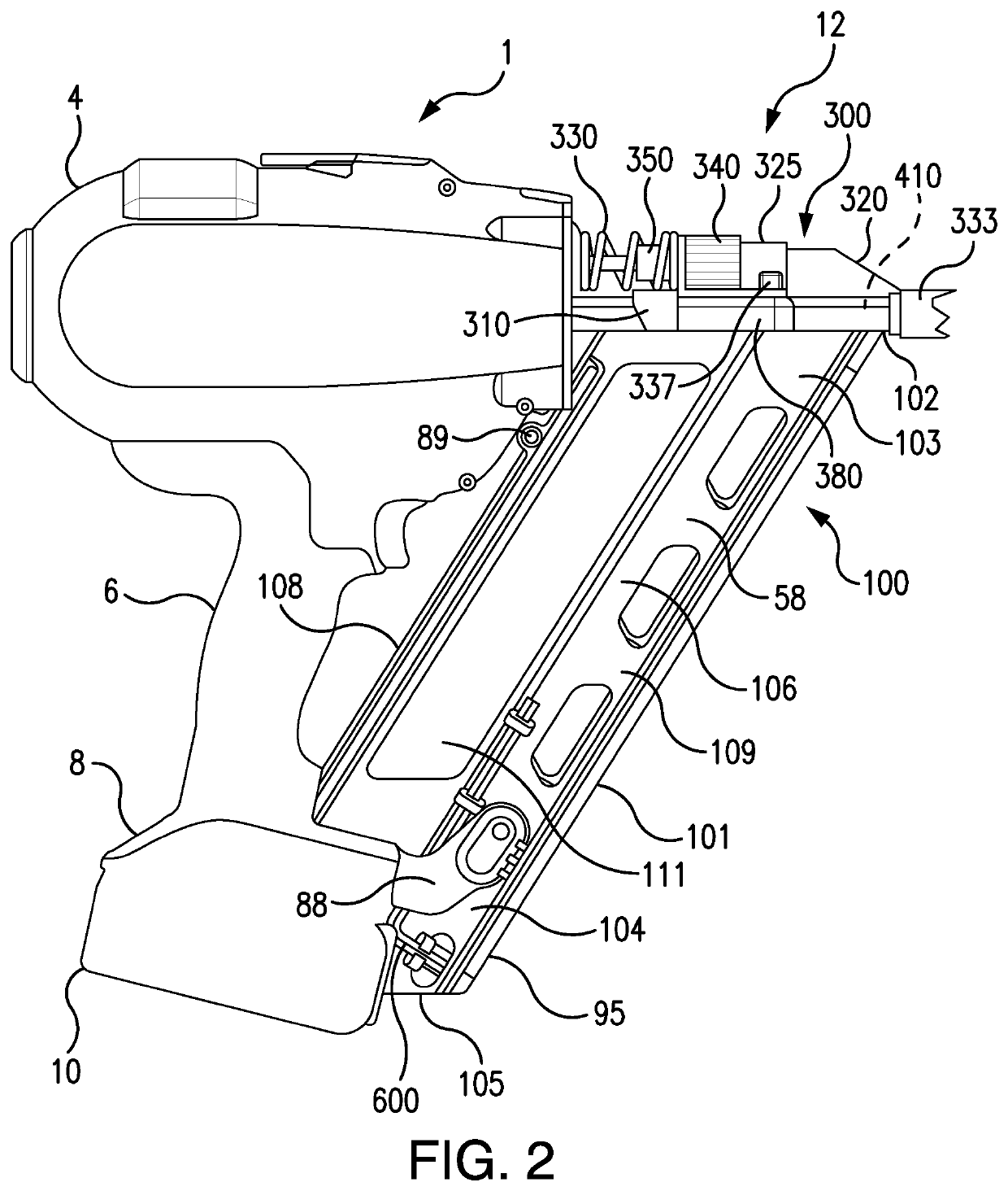
[0008]A power tool, such as a fastening tool, can have one or more sound damping members which can control, manage, reduce and eliminate undesired sound and / or noise emitted from such tools. Herein, “sound” and “noise” are used synonymously.

Problems solved by technology

However, many fastening tools which are available are insufficient in design, expensive to manufacture, heavy, not energy efficient, lack power, have dimensions which are inconveniently large and cause operators difficulties when in use.
Further, many available fastening tools do not adequately guard the moving parts of a nailer driving mechanism from damage. operators difficulties when in use.
Further, many available fastening tools do not adequately guard the moving parts of a nailer driving mechanism from damage.
Additionally, many power tools, such as fastening tools, emit excess sound and / or noise.
Such excess sound and / or noise can be unpleasant to the user and others within a hearing distance thereof.
Further, many fastening tools which are available are inconveniently bulky and have systems for driving a fastener which have dimensions that require the fastening tool to be larger than desired.
For example, drive systems having a motor which turns a rotor can require clutches, transmissions, control systems and kinetic parts which increase stack up and limit the ability of a power tool to be reduced in size while retaining sufficient power to achieve a desired performance.

Method used


Image

  • Sound damping for power tools
  • Sound damping for power tools
  • Sound damping for power tools

Examples


example 1 and example 2

[0219]FIGS. 29 through 36 collectively relate to Example 1 and Example 2. FIG. 29 shows the cupped flywheel without a sound damping member tested in Example 1. FIG. 30 shows of the cupped flywheel having a sound damping member tested in Example 2. FIGS. 31 through 36 collectively regard data and results from Example 1 and Example 2.

[0220]Example 1 and Example 2 regard comparative testing between a cupped flywheel 702 without a sound damping member 1015 and a cupped flywheel with a sound damping member 1015. The embodiment of the sound damping member 1015 tested in Example 1 and Example 2 is a vibration absorption member 1020.

[0221]Example 1 and Example 2 followed a Vibration And Sound Evaluation Procedure (“VASE Procedure”) which has the following steps:

[0222]Step 1. Suspend a part by a means that does not influence the vibration and sound reaction and / or response (string, small wire, etc.) when the part, such as the cupped flywheel 702, is struck by a modal hammer 2530. As shown in...


PUM


Abstract

A power tool having one or more sound damping members which reduce sound and / or vibration from one or more parts of a power tool. The sound damping member can reduce sound and / or vibration from static or dynamic parts of a power tool. The sound damping member can reduce noise and / or vibration from one or more rotating or moving parts of a power tool and its housing or internal structure. Methods, means, controls, systems and practices for reducing or eliminating undesired sound from a power tool are disclosed.

Description

CROSS-REFERENCE TO RELATED APPLICATIONS[0001]This patent application is a continuation-in-part of and claims benefit of the filing date of copending U.S. patent application Ser. No. 14 / 444,982 entitled “Power Tool Drive Mechanism” filed Jul. 28, 2014. This application is also a continuation of PCT Application No. PCT / CN2015 / 076257 entitled “Sound Damping for Power Tools” filed Apr. 10, 2015.FIELD OF THE INVENTION[0002]The present invention relates to sound damping for power tools.INCORPORATION BY REFERENCE[0003]This patent application incorporates by reference in its entirety copending U.S. patent application Ser. No. 14 / 444,982 entitled “Power Tool Drive Mechanism” filed Jul. 28, 2014 and PCT Application No. PCT / CN2015 / 076257 entitled “Sound Damping for Power Tools” filed Apr. 10, 2015.BACKGROUND OF THE INVENTION[0004]Fastening tools, such as nailers, are used in the construction trades. However, many fastening tools which are available are insufficient in design, expensive to manu...

Claims


Application Information

Patent Timeline
Patent Type & Authority Patents(United States)
IPC IPC(8): B25C1/06B25F5/00
CPCB25C1/06B25F5/00
Inventor KOENIG, TREVOR J.CANNALIATO, MICHAEL F.KUEHNE, BRENT A.RETH, ANTHONYMONDICH, NICHOLAS A.MCCLASKEY, STEVENWANG, XIN LEICHEN, YUFENGGROSS, PAUL G.MATTUCCI, MARCO ALESSANDROBASKAR, ASHOK SAMUEL
Owner BLACK & DECKER INC
Why Eureka
Try Eureka