Electrical appliance, in particular hand-held power tool

Inactive Publication Date: 2011-09-15
ROBERT BOSCH GMBH
View PDF57 Cites 305 Cited by
  • Summary
  • Abstract
  • Description
  • Claims
  • Application Information

AI Technical Summary

Benefits of technology

[0010]In order to position the flexible sealing element inside the housing, according to a proposed preferred embodiment, the sealing element is fastened to a first support element that is situated on an inner wall of the appliance housing. As a result, the sealing element can be integrated into the housing of the electrical appliance during a pre-assembly process of the electrical appliance and removing the circuitry substrate from the housing does not also require removal of the sealing element.
[0011]In this case, it is particularly preferable if the first support element is embodied of one piece with the appliance housing, in particular by being injection-molded onto the appliance housing. This has the particular advantage that with a conventional embodiment of the appliance housing in the form of an injection-molded plastic component, the mold of the first support element can already be integrated into or taken into account in the mold for manufacturing the appliance housing so that embodying the first support element essentially incurs no additional costs.
[0012]According to another proposal, the first support element has a recess for accommodating the sealing element in a form-locked manner. This enables a simple installation of the sealing element and, in the event of damage, a simple replacement of the sealing element on the support element.
[0013]In order to enable a simpl

Problems solved by technology

In such electrical appliances, it is also known to provide a sealing element embodied in the form of ribs inside the housing shells in order to prevent the pen

Method used


Image

  • Electrical appliance, in particular hand-held power tool
  • Electrical appliance, in particular hand-held power tool
  • Electrical appliance, in particular hand-held power tool

Examples


Embodiment Construction

[0019]In the figures, parts that are the same or function in the same manner are provided with identical reference numerals.

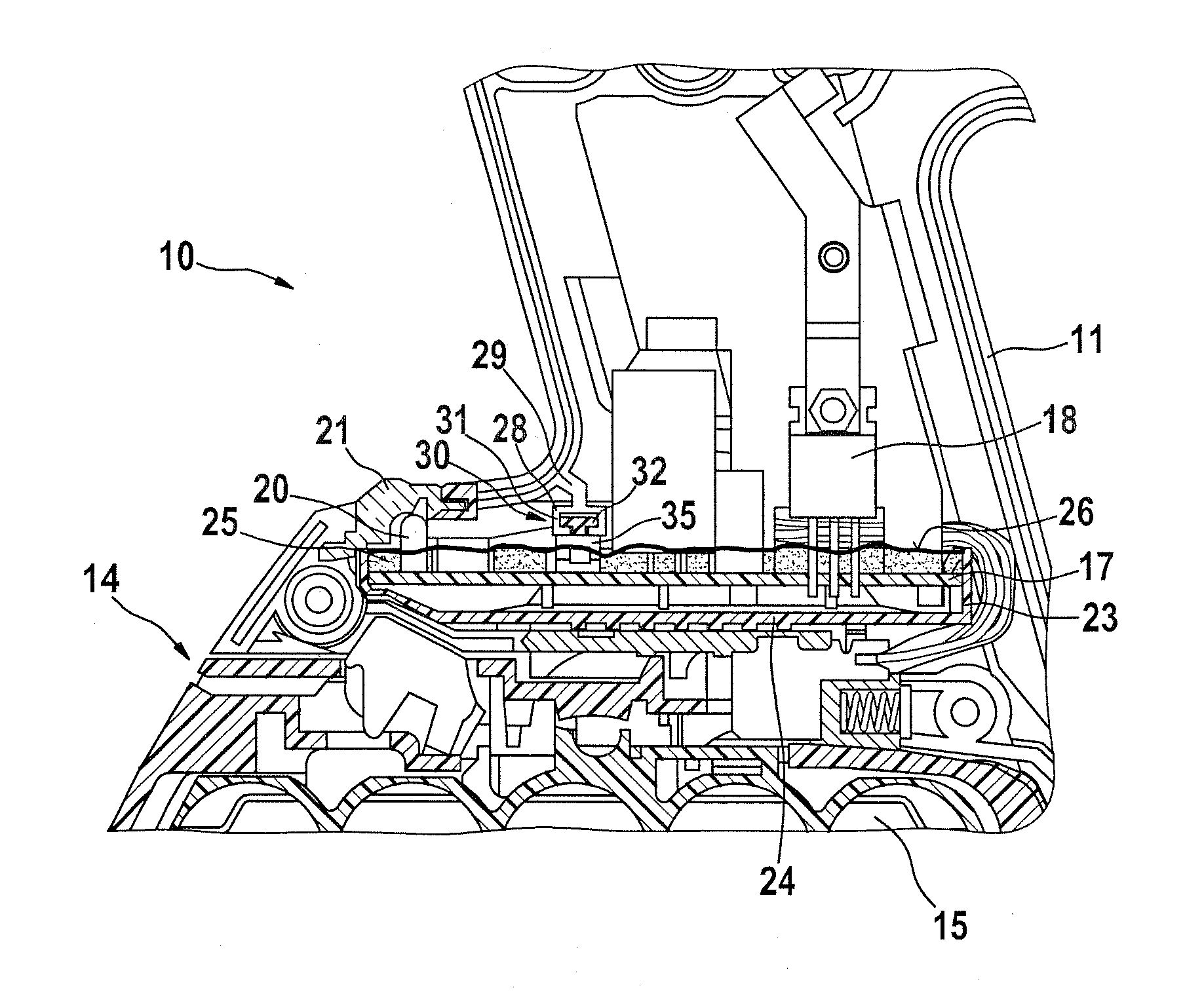
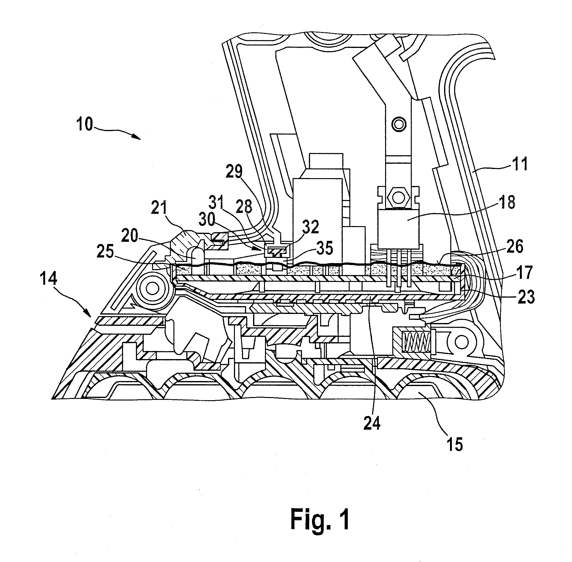
[0020]The figures show a subregion of an electrical appliance 10 according to the invention, in particular a hand-held power tool. For example, the electrical appliance 10 can be a drill that is known in the building trades or some other hand-held power tool.

[0021]The electrical appliance 10 has a housing 11 that is composed, for example, of two housing shells that are not shown in greater detail. The housing 11 or more precisely, the housing shells, is / are in particular composed of plastic and manufactured using the injection-molding process. The components of the electrical appliance 10 are contained inside the housing 11 or housing shells.

[0022]In the lower region of the housing 11, the drawing shows an accommodating region 14 for accommodating an in particular replaceably embodied energy storage device, e.g. in the form of a battery pack 15. The drawing als...


PUM


Abstract

The invention relates to an electrical appliance, in particular a hand-held power tool, having an appliance housing, a circuitry substrate that is situated in the appliance housing and equipped with components, and sealing elements for preventing the influx of dirt into the region of the circuitry substrate. According to the invention, the sealing elements seal a subregion of the circuitry substrate off from other regions inside the appliance housing.

Description

CROSS-REFERENCE TO RELATED APPLICATION[0001]This application is based on German Patent Application 10 2010 002 702.2 filed on Mar. 9, 2010.BACKGROUND OF THE INVENTION[0002]1. Field of the Invention[0003]The invention relates to an electrical appliance, in particular a hand-held power tool.[0004]2. Description of the Prior Art[0005]An electrical appliance of this kind known from the prior art has, for example, a housing that is composed of two housing shells inside which are accommodated the drive unit of the electrical appliance and the electrical circuitry for the drive unit. Examples of this include drills, grinders, or similar hand-held power tools. In such electrical appliances, it is also known to provide a sealing element embodied in the form of ribs inside the housing shells in order to prevent the penetration of dust or other impurities since such impurities make it impossible to ensure reliable function of the electrical appliance over a long service life. It is also known ...

Claims


Application Information

Patent Timeline
IPC IPC(8): B25F5/02F16J15/02
CPCB25F5/02
Inventor FRIESE, ANDREASKYNAST, ANDREASSCHLEGEL, ANDREAS
Owner ROBERT BOSCH GMBH
Why Eureka
Try Eureka