Anti-blocking device for coal falling region of coal-fired boiler

A technology for coal-fired boilers and regions, applied in the field of coal feeding of coal-fired boilers, can solve the problems of thinning wall thickness, increased coal blocking frequency, high labor intensity, etc., so as to reduce impact and wear, prolong service life, and reduce charging into the furnace. amount of effect

Inactive Publication Date: 2012-08-22
YANKUANG LUNAN CHEM FERTILIZER PLANT
View PDF4 Cites 0 Cited by
  • Summary
  • Abstract
  • Description
  • Claims
  • Application Information

AI Technical Summary

Problems solved by technology

[0002] In the existing coal feeding device for circulating fluidized bed boilers, the coal with a certain speed and quality first impacts the coal falling area on the coal sliding pipe during the falling process, which causes increased wear and tear in this area and long-term operation. Not only will there be local pits, which will increase the roughness and reduce the wall thickness, but also the finer coal will not easily slide and accumulate in this area, which will eventually lead to the occurrence of coal blocking
In addition, excessive moisture in coal will further increase the frequency of coal blocking
Although there is a coal conveying wind on the coal sliding pipe when the boiler is manufactured, the actual operation effect is not ideal
[0003] In the process of dealing with coal slipping and coal blocking, the boiler often needs to be operated at reduced load. If it is not handled properly during this period, coking accidents may occur, which will seriously affect the stable operation of the boiler and the pressure of the steam system pipe network.
The method of dredging the coal blockage is usually manual use of simple tools for pounding, which is not only labor-intensive, but also has the hidden danger of being scalded

Method used


Image

  • Anti-blocking device for coal falling region of coal-fired boiler
  • Anti-blocking device for coal falling region of coal-fired boiler
  • Anti-blocking device for coal falling region of coal-fired boiler

Examples


Embodiment 1

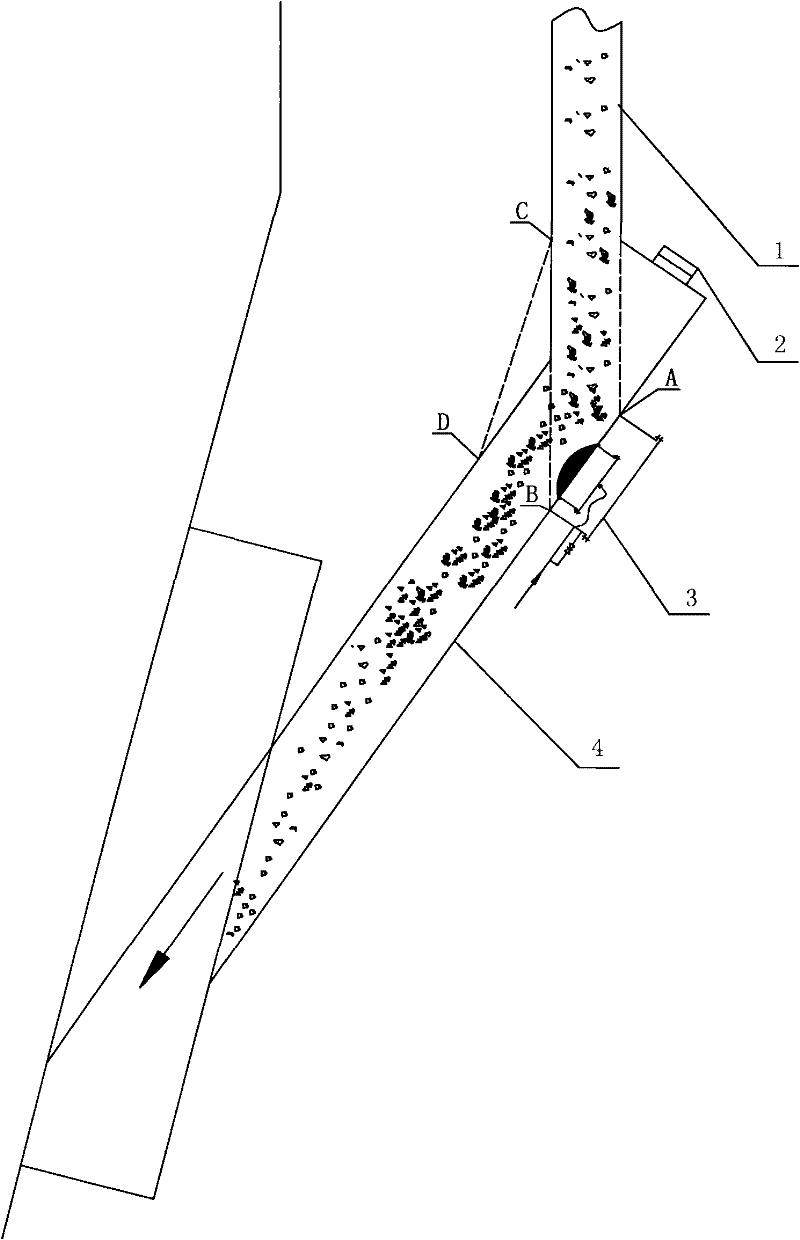
[0028] Draw a vertical line at both ends of the coal drop pipe 1, and pass the coal drop pipe 4 at two points A and B, that is, the coal drop area is A-B. A fluidization device is installed in this area, and the pressure to the inner air chamber is 0.1-0.3 Mpa, fluidizing air with a temperature of 90-260°C, the pressure is controlled to make the force exerted by the air on the particles equal to the gravity of the coal particles through the fluidization, so that the coal is in a suspended state, and the non-contact turning is realized in the coal falling area to prevent blockage Coal occurs.

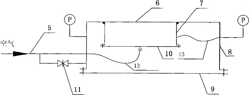
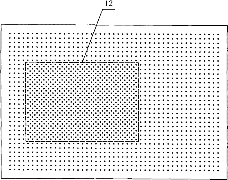
[0029] In addition, in order to avoid blockage of the small holes of the fluidized plate itself, the air chamber and the bottom plate in the present invention are connected by flanges, which can be disassembled for inspection and cleaning if necessary.


PUM


Abstract

The invention discloses an anti-blocking device for a coal falling region of a coal-fired boiler. The bottom of the coal falling region is provided with the anti-blocking device for the coal falling region of the coal-fired boiler. The device comprises an air chamber formed by encircling a fluidization plate, a side plate and a bottom plate, wherein an inner air chamber formed by encircling an inner side plate, an inner bottom plate and a partial fluidization plate is arranged in the air chamber and is communicated with a fluidization air pipe outside the air chamber through a metal hose; andsmall fluidization holes are densely formed on the fluidization plate. Coal can turn in a noncontact form while sliding from the coal falling region to a coal falling oblique pipe, so that coal accumulation is avoided and coal blocking is prevented. Secondly, impact and wear of the coal falling region are reduced and the service life of a coal sliding pipe is prolonged; moreover, coal is fully contacted with high-temperature fluidization air in a fluidization region, so that coal is dried and is prevented from being blown onto the other side by the fluidization air and being attached to a pipe wall, so that the anti-blocking aim is fulfilled; and lastly, due to the supply of the fluidization air, the feeding amount of external cold air can be decreased greatly and the coal sliding pipe issealed by gas to a certain extent.

Description

Technical field: [0001] The invention relates to an anti-blocking device for a coal-falling area of ​​a coal-fired boiler, belonging to the technical field of coal-feeding for a coal-fired boiler. Background technique: [0002] In the existing coal feeding device for circulating fluidized bed boilers, the coal with a certain speed and quality first impacts the coal falling area on the coal sliding pipe during the falling process, which causes increased wear and tear in this area and long-term operation. Not only will local pits be produced, the roughness will increase and the wall thickness will be thinned, but the finer coal will not easily slide and accumulate in this area, which eventually leads to the occurrence of coal blocking. In addition, excessive moisture in coal will further increase the frequency of coal blocking. Although there is a coal conveying wind on the coal-sliding pipe when the boiler is manufactured, the actual operation effect is not ideal. [0003] ...

Claims


Application Information

Patent Timeline
Patent Type & Authority Patents(China)
IPC IPC(8): F23C10/18
Inventor 张永祥颜芳叶盛芳赵文宋燕司品义沈尚超
Owner YANKUANG LUNAN CHEM FERTILIZER PLANT
Why Eureka
Try Eureka