Workbench

A workbench and fixed platform technology, which is applied to conveyor objects, transportation, and packaging, etc., can solve the problems of time-consuming and low efficiency, and achieve the effect of assembly line.

Active Publication Date: 2012-07-04
SHANGHAI MUNICIPAL ELECTRIC POWER CO +1
View PDF0 Cites 0 Cited by
  • Summary
  • Abstract
  • Description
  • Claims
  • Application Information

AI Technical Summary

Problems solved by technology

However, this manual process of threading the pins is very time-consuming and inefficient, so it is urgent to provide a machine that can automatically thread the pins and the supporting parts therein

Method used


Image

  • Workbench
  • Workbench
  • Workbench

Examples


Embodiment Construction

[0020] In order to make the purpose, technical solutions and advantages of the embodiments of the present invention clearer, the technical solutions in the embodiments of the present invention will be clearly and completely described below in conjunction with the drawings in the embodiments of the present invention. Obviously, the described embodiments It is a part of embodiments of the present invention, but not all embodiments. Based on the embodiments of the present invention, all other embodiments obtained by persons of ordinary skill in the art without making creative efforts belong to the protection scope of the present invention.

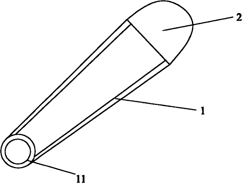
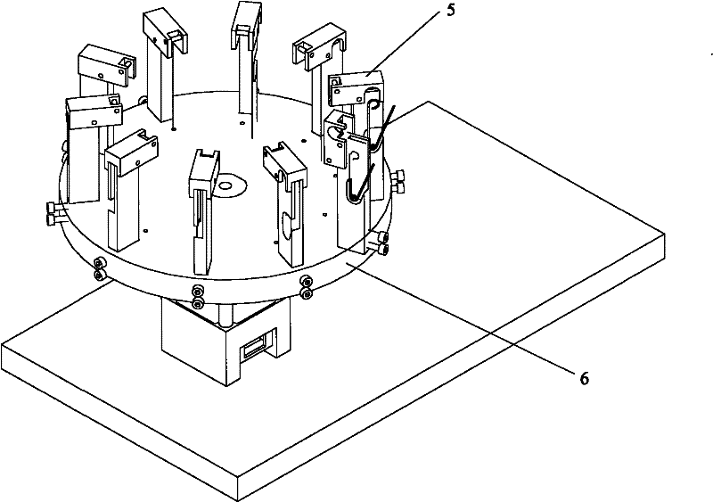
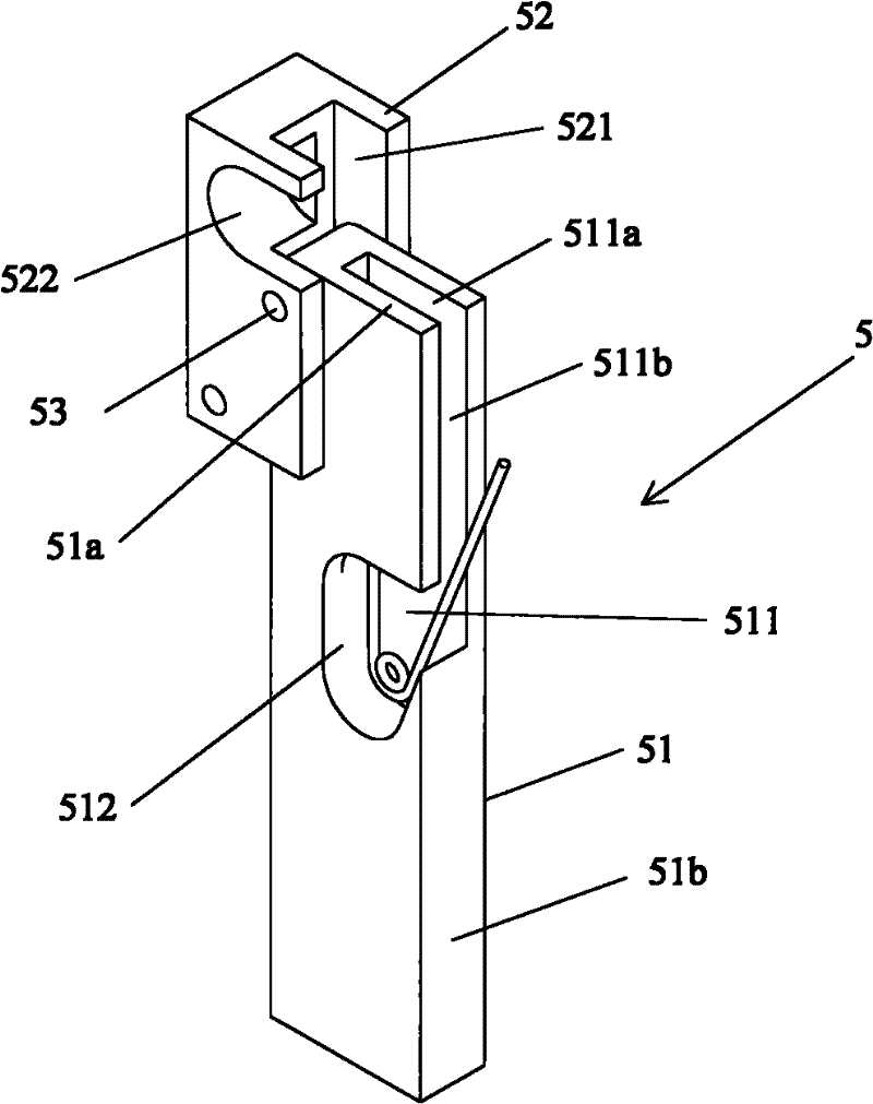
[0021] figure 2 An isometric view of the workbench provided for the embodiment of the present invention. The workbench includes a rotating platform 6 and at least one fixing frame 5 installed on the circumference of the upper surface of the rotating platform 6 . The fixing frame 5 is used to fix the wearing pins. The rotating platform 6 c...


PUM


Abstract

The embodiment of the invention provides a workbench which comprises a rotating platform and at least one fixing frame arranged on the circumference of the upper surface of the rotating platform, wherein the fixing frames are used for penetrating and fixing pins, and each fixing frame comprises an accommodating part; an accommodating groove is formed in each accommodating part, and the shapes of the accommodating grooves correspond to the shapes of pins of which the steel needles are separated from snap rings; at the moment, the snap rings of the pins are upward, and curling parts of the pinsare butted against the bottom of the accommodating groove; each accommodating groove is respectively provided with an opening on the top surface of the accommodating part and the side surface facing towards the steel needle separating end of the pin in the accommodating groove; and the side surface of the accommodating part with the accommodating groove faces towards the radial outward direction of the rotating platform. The workbench can ensure that penetrated and fixed pins can move among different stations so as to realize the line production of a pin penetrating process.

Description

technical field [0001] The invention belongs to the technical field of pin processing, and in particular relates to a rotary conveying device used in a pin threading machine. Background technique [0002] There are many kinds of existing pins, and their uses are also different. The structure of one of the more common pins is as follows: figure 1 As shown, the pin is composed of a bent steel needle 1 and a buckle 2, wherein both ends of the steel needle 1 are located in the buckle 2, and one end can be detached from the buckle 2. The middle part of the steel needle 1 is curled into at least one circle to form a curled portion 11 . [0003] in will figure 1 After the production of the pins is completed, in order to facilitate transportation and sale, the pins need to be worn, that is, the curled parts 11 of multiple pins are passed through one pin, so that a series of pins can be easily taken, and it is also relatively space-saving Program. At present, the above pin wearin...

Claims


Application Information

Patent Timeline
Patent Type & Authority Patents(China)
IPC IPC(8): B65G47/80
Inventor 张莉
Owner SHANGHAI MUNICIPAL ELECTRIC POWER CO
Why Eureka
Try Eureka