
Radiating element for a signal emitting apparatus

A technology of transmitting device and radiating element, applied in the field of antenna and electronic signal transmitting device, can solve the problems of unsuitable use of metal antenna and increased cost of products, etc.

Inactive Publication Date: 2014-07-16
KIMBERLY-CLARK WORLDWIDE INC
View PDF33 Cites 0 Cited by
  • Summary
  • Abstract
  • Description
  • Claims
  • Application Information

AI Technical Summary

Problems solved by technology

However, some problems are encountered when incorporating antennas into consumer goods, other products, or the packaging in which the product is placed for shipping and sale
Metal antennas are not suitable for example in some products
Additionally, many previously recommended antennas add considerable cost to the product

Method used


Image

  • Radiating element for a signal emitting apparatus
  • Radiating element for a signal emitting apparatus
  • Radiating element for a signal emitting apparatus

Examples


example 1

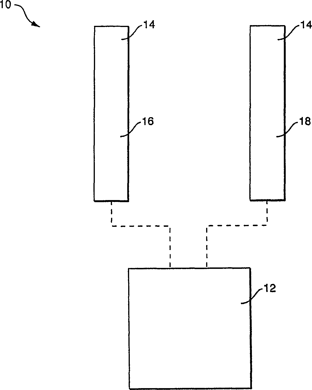
[0084] Conductive nonwoven webs were made according to the invention and tested as antennas. Specifically, half-wave dipole antennas were constructed from conductive nonwoven webs made according to the present invention and tested for their ability to transmit signals.

[0085] In this example, two identical strips of conductive paper material made according to the invention were attached to a pre-antenna substrate and connected to a signal generator. The strip of conductive paper material contains carbon fibers and forms a half-wave dipole antenna. The antenna is designed to radiate at 915MHz. The effective length of the antenna is 164mm. A simple test of the radiated power of the antenna. The signal generator delivers a 10dBm signal from the antenna at 900MHz. The received signal was measured using a 900 MHz calibrated antenna connected to a spectrum analyzer placed 1 meter from the antenna.

[0086] The conductive nonwoven web used to form the antenna included an uncre...

example 2

[0091] Attach the half-wave dipole antenna constructed in Schematic 1 to the prefabricated RFID tape. This RFID strip operates in the UHF range. The sensitivity of the antenna made of conductive web was measured by monitoring the power, which is the minimum power required by the RFID tape to respond to an RFID reader antenna located 1 meter away. The estimated sensitivity of the antenna is -5.1 dBm, which is sufficient for efficient readout.


PUM

PropertyMeasurementUnit
electrical conductivityaaaaaaaaaa
lengthaaaaaaaaaa
lengthaaaaaaaaaa

Abstract

A radiating element made of an electrically conductive nonwoven web is incorporated into the signal emitting device. The signal transmitting device may comprise an RFID tag, for example. In one embodiment, the conductive nonwoven web includes conductive fibers combined with pulp fibers. The conductive fibers include carbon fibers. Nonwoven webs can be produced using conventional papermaking methods. The resulting conductive fiber mesh is not only well suited for use as an antenna, but is also cheap to manufacture and easy to incorporate into many products.

Description

Background technique [0001] Advances in miniaturization have led to the development of small electronic devices for sensing many different parameters. Likewise, advances in wireless communication technology combined with more popular interconnected computer systems, such as the Internet, have provided the technology needed to inexpensively transfer large amounts of data between two or more computers. This combination of technologies provides the ability to monitor, track and communicate using small sensors and processors. [0002] For example a radio frequency identification device (RFID) is a low cost "smart" chip or "tag" that can be embedded or attached to an item, product, etc. to convey information about the product via a scanner. The smart label is usually a small tag-like device with a microchip and a tiny embedded antenna. The tag can be passive or active, with active tags requiring an internal power source. A reader or scanner interrogates the smart tag with an ele...

Claims


Application Information

Patent Timeline
Patent Type & Authority Patents(China)
IPC IPC(8): B32B33/00H01Q1/12G06K19/077
CPCY10T428/2927B32B33/00B32B2519/02H01Q1/273Y10T428/2925B32B2305/20B32B2459/00Y10T428/2924B32B2535/00H01Q1/2225H01Q9/285A41D13/1281
Inventor S·盖克哈尔D·J·舒克斯基T·M·阿莱斯S·J·沙利文A·M·朗D-D·H·恩汉S·兰加纳坦
Owner KIMBERLY-CLARK WORLDWIDE INC
Learn More