Electric pay-off rack

A pay-off frame and electric technology, applied in the direction of cable laying equipment, etc., can solve the problems of affecting economic and social benefits, delaying project progress, and long construction period, so as to achieve a solid overall structure, reduce labor intensity, and high work efficiency Effect

Active Publication Date: 2011-05-11
STATE GRID CORP OF CHINA +1
View PDF0 Cites 4 Cited by
  • Summary
  • Abstract
  • Description
  • Claims
  • Application Information

AI Technical Summary

Problems solved by technology

This method of manually lowering cables has high labor intensity, low work efficiency, and long construction period, which will seriously delay the progress of the project, thereby affecting economic and social benefits.

Method used


Image

  • Electric pay-off rack
  • Electric pay-off rack

Examples


Embodiment Construction

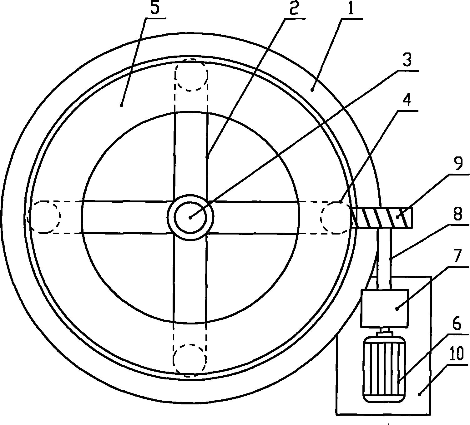
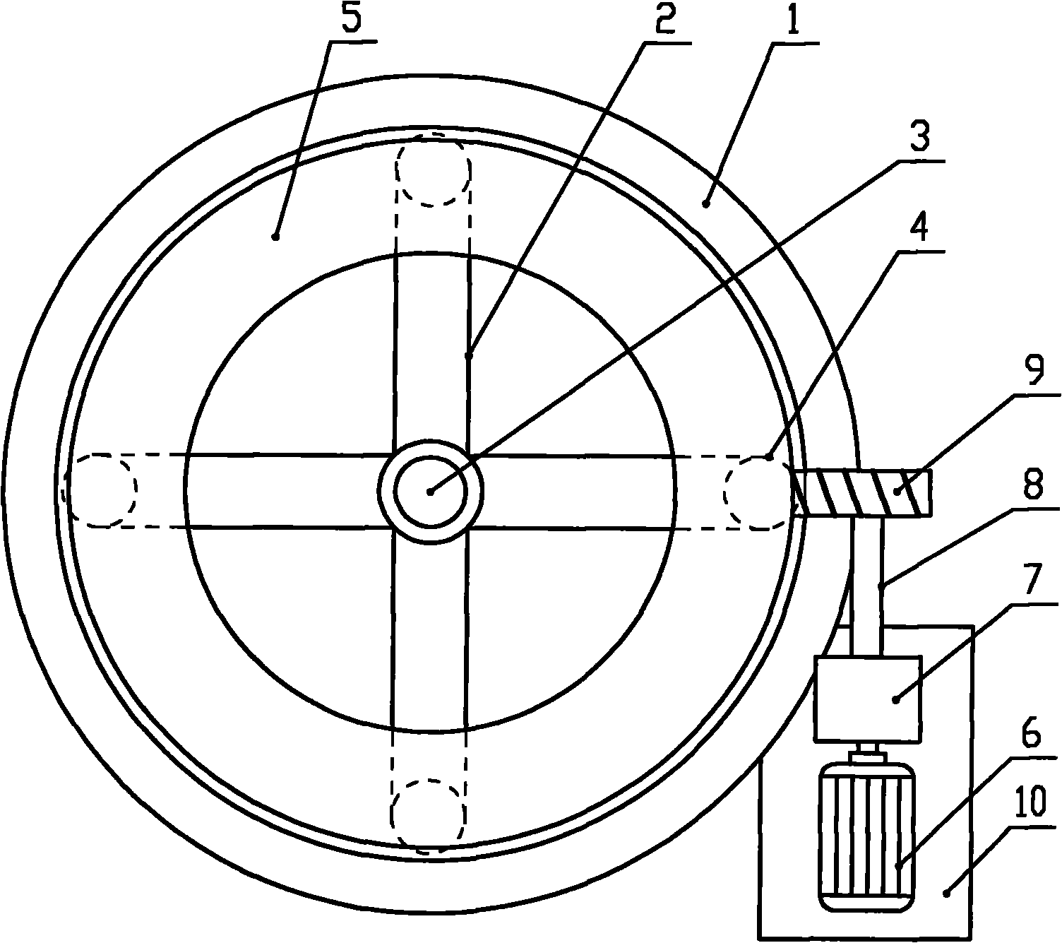
[0015] Such as figure 1 As shown, the electric pay-off stand of the present invention includes a base plate 1 and a horizontal rotation device, the horizontal rotation device is arranged on the base plate 1 and connected in rotation with the base plate 1, and the horizontal rotation device is connected with a power drive device. The horizontal rotation device includes a support frame 2, the center of the support frame 2 is provided with a main shaft 3 vertically fixedly connected to the base plate 1, the support frame 2 is connected to the main shaft 3 in rotation, and the lower part of the support frame 2 is evenly equipped with four shafts with the axis of the main shaft 3 as the central axis. The roller 4 and the upper part of the support frame 2 are horizontally provided with a support plate 5 with the axis of the main shaft 3 as the central axis, and the outer circumference of the support plate 5 is a helical tooth structure. The power drive device includes a motor 6 and ...


PUM


Abstract

The invention discloses an electric pay-off rack which comprises a bottom plate and a horizontal rotating device. The horizontal rotating device is arranged on a bottom plate and is connected with the bottom plate in a rotation mode; and the horizontal rotating device is connected transmittedly with a power driving device. In the invention, the design is reasonable, the structure is simple, an automatic release rack is provided for the pay-off cable, the labor intensity of workers is reduced fully, the work efficiency is improved, the construction cycle is shortened, the practicability is strong, and the electric pay-off rack is easy to popularize and apply.

Description

technical field [0001] The invention belongs to the technical field of electric power industry construction, and in particular relates to an electric pay-off frame for lowering cables. Background technique [0002] In the construction of the power industry, it is generally necessary to lower the entire cable and then install the cable. At present, manual work is generally used in the construction of the entire cable tray. One of the lowering methods is: a rotating shaft is inserted into the center of the cable tray, and the rotating shaft is set horizontally. Both ends are supported by brackets, and then the cable tray is manually rotated. Carry out cable lowering operations; another lowering method is to set the cable reel axially vertically, place it on a chassis that can rotate horizontally, and still rely on manual rotation of the cable reel to perform cable lowering operations. This kind of operation method of manually lowering cables has high labor intensity, low work...

Claims


Application Information

Patent Timeline
Patent Type & Authority Applications(China)
IPC IPC(8): H02G1/06
Inventor 王来军郭伟伟
Owner STATE GRID CORP OF CHINA
Why Eureka
Try Eureka