Lead guidance device

A guiding device and wire technology, which is applied in the installation of cables, the arrangement of cables between relative moving parts, and electrical components, etc. The folding position cannot be as expected, etc., to avoid jamming or squeezing other components or peripheral electronic devices, and to eliminate the effect of winding

Inactive Publication Date: 2011-05-11
INVENTEC CORP
View PDF0 Cites 5 Cited by
  • Summary
  • Abstract
  • Description
  • Claims
  • Application Information

AI Technical Summary

Problems solved by technology

Due to the long length of the wires, the way and position of the wires cannot be folded as expected during the process of pushing the box into the casing, and sometimes the box may be stuck so that the box cannot be pushed into the casing, or Extruded into surrounding electronic components, or entangled with other wires

Method used


Image

  • Lead guidance device
  • Lead guidance device
  • Lead guidance device

Examples


Embodiment Construction

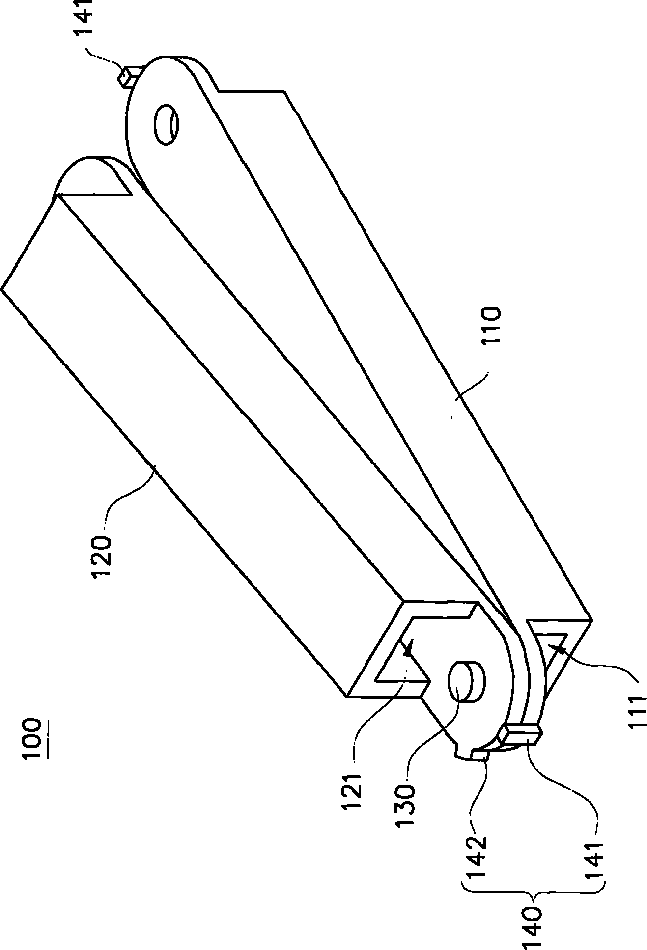
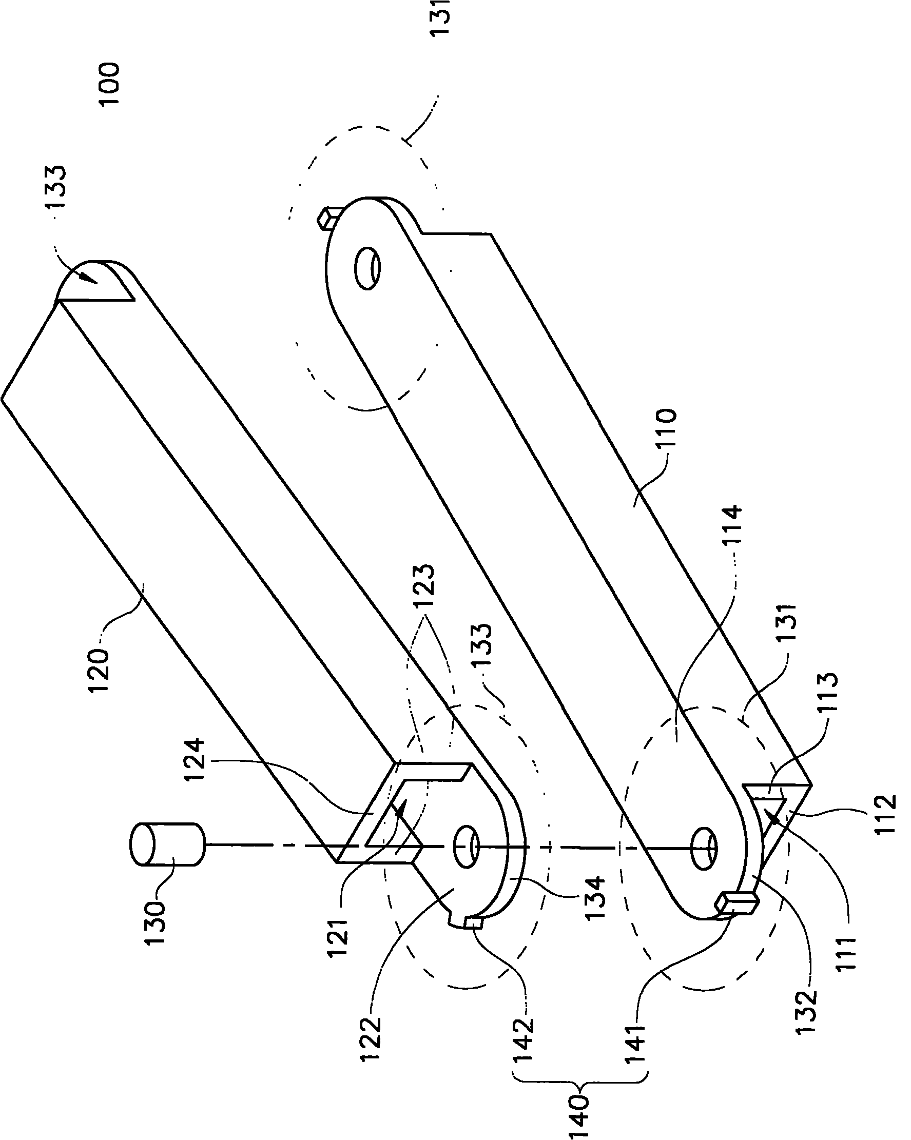
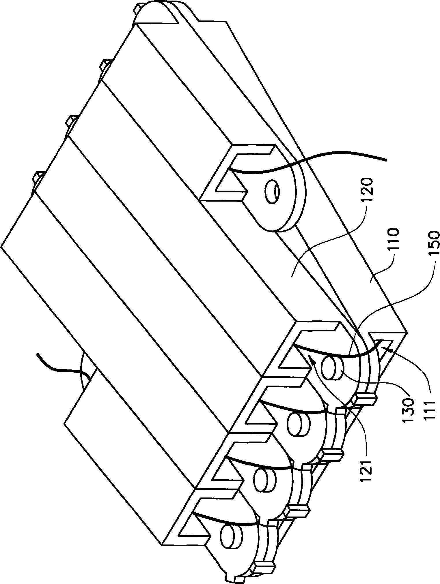
[0033] Please also refer to figure 1 and figure 2 . figure 1 and figure 2 A perspective view and an exploded view of the wire guiding device 100 according to an embodiment of the present invention are shown respectively. The wire guiding device 100 of the present invention has a first protective tube 110 , a second protective tube 120 and a pivot 130 . The first protective tube 110 has a first accommodating channel 111 in its longitudinal direction, and two ends of the first protective tube 110 respectively have a first pivot portion 131 . The second protective tube 120 has a second accommodating channel 121 in its longitudinal direction, and each of the two ends of the second protective tube 120 has a second pivot joint 133, through which the second pivot joint 133 at one end of the second protective tube 120 is overlapped. The first pivotal portion 131 at one end of the first protection tube 110 . The pivot 130 passes through the first pivot portion 131 and the second...


PUM


Abstract

The invention relates to a lead guidance device which is provided with a first protection pipe, a second protection pipe and a pivot, a pivot jointing part at one end of the second protection pipe is spliced to the pivot jointing part at one end of the first protection pipe and then the pivot penetrates through the pivot jointing parts, so that the second protection pipe can rotate pivotedly around the pivot relative to the first protection pipe; a lead penetrates through the first protection pipe and the second protection pipe to unfold or fold the lead through a relative pivoting rotation mode of the first protection pipe and the second protection pipe to protect the lead from being collided or broken.

Description

technical field [0001] The present invention relates to a wire guiding device, and in particular to a guiding device capable of expanding or retracting a wire. Background technique [0002] Generally speaking, multiple electronic devices such as hard disks, optical drives, processors or fans are usually loaded in a large computer. In order to facilitate assembly, a connector is usually installed at the installation position of the machine, and the connector is electrically connected to the power supply, and the electronic device can obtain power after being connected to the connector. On the other hand, the electronic device can also be electrically connected to the circuit board in the machine through the connector. [0003] At present, most common machines adopt a hot-swap design structure, which means that the connection between the connector and the power supply adopts a re-swappable design. Taking a rack server as an example, the machine platform of the rack server ha...

Claims


Application Information

Patent Timeline
Patent Type & Authority Applications(China)
IPC IPC(8): H02G11/00H02G1/08
Inventor 魏家鸿陈佩钰
Owner INVENTEC CORP
Why Eureka
Try Eureka