Anti-collision positioning device for laser machining of metal part

A laser processing and positioning device technology, applied in metal processing equipment, laser welding equipment, manufacturing tools, etc., can solve the problems of single positioning device mechanism and damage, and achieve the effect of protecting components and facilitating installation.

Inactive Publication Date: 2021-03-12
王华根
View PDF0 Cites 0 Cited by
  • Summary
  • Abstract
  • Description
  • Claims
  • Application Information

AI Technical Summary

Problems solved by technology

[0003] However, the existing laser positioning device for metal parts adopts a single positioning device mechanism, and the laser cutting equipment connected to the existing positioning device exposes the laser cutting equipment to the outside when it is in use or not. , is easily damaged by the impact of other components, and does not meet the existing needs. For this, we propose a positioning device for laser processing of metal parts. For this reason, we propose a positioning device for laser processing of metal parts with anti-collision

Method used


Image

  • Anti-collision positioning device for laser machining of metal part
  • Anti-collision positioning device for laser machining of metal part
  • Anti-collision positioning device for laser machining of metal part

Examples


Embodiment Construction

[0021] The following will clearly and completely describe the technical solutions in the embodiments of the present invention with reference to the accompanying drawings in the embodiments of the present invention. Obviously, the described embodiments are only some, not all, embodiments of the present invention. Based on the embodiments of the present invention, all other embodiments obtained by persons of ordinary skill in the art without making creative efforts belong to the protection scope of the present invention.

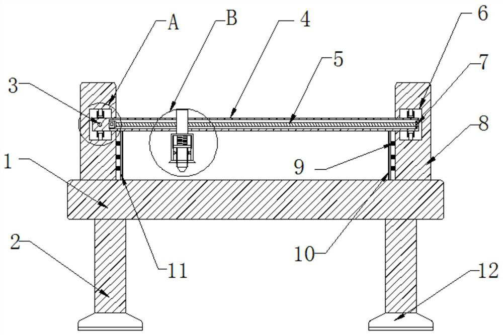
[0022] see figure 1 , the present invention provides a technical solution: a collision-proof positioning device for laser processing of metal parts, including a processing table 1, the four corners of the lower end surface of the processing table 1 are provided with supporting columns 2, and the lower end surfaces of the supporting columns 2 are equipped with installation Seat 12, the left and right sides of the upper end surface of the processing table 1 are ...


PUM


Abstract

The invention discloses laser processing auxiliary equipment, and relates to an anti-collision positioning device for laser machining of a metal part. The anti-collision positioning device comprises amachining table, supporting columns are arranged at the four corners of the lower end face of the machining table correspondingly, mounting bases are arranged on the lower end faces of the supportingcolumns correspondingly, and fixing plates are arranged at the left side and the right side of the upper end face of the machining table correspondingly; T-shaped grooves are formed in the middles ofthe opposite faces of the fixing plates correspondingly, openings of the T-shaped grooves correspond to each other, a longitudinal transmission device is arranged in an inner cavity of the T-shaped groove in the left side and transversely sleeved with a transverse pipe, sliding devices are arranged at the left side and the right side of the transverse pipe correspondingly, and the right side of the transverse pipe is installed at the inner side of the T-shaped groove in the right side; and the left end face of an inner cavity of the transverse pipe is fixedly connected with a transverse servomotor, a motor shaft of the transverse servo motor is fixedly connected with a transverse threaded rod, and the outer wall of the right end of the transverse threaded rod is fixedly connected with atransverse fixing bearing. The anti-collision positioning device is simple in structure and convenient to operate, a laser head is effectively protected, and the service life of the laser head is prolonged.

Description

technical field [0001] The invention relates to the technical field of laser processing auxiliary equipment, in particular to an anti-collision positioning device for laser processing of metal parts. Background technique [0002] The laser cutting machine focuses the laser emitted from the laser into a high-power-density laser beam through the optical path system. The laser beam irradiates the surface of the workpiece to make the workpiece reach the melting point or boiling point. At the same time, the high-pressure gas coaxial with the beam will melt or The vaporized metal is blown away, and with the movement of the relative position of the beam and the workpiece, the material finally forms a slit, so as to achieve the purpose of cutting. Laser cutting process uses an invisible beam to replace the traditional mechanical knife, which has high precision and cutting Fast, not limited to cutting patterns, automatic typesetting saves materials, smooth incision, low processing co...

Claims


Application Information

Patent Timeline
Patent Type & Authority Applications(China)
IPC IPC(8): B23K26/38B23K26/70B23K26/08
CPCB23K26/0876B23K26/38B23K26/702
Inventor 王华根
Owner 王华根
Why Eureka
Try Eureka