

Method and device for protecting point-to-multipoint pseudo-wire
A pseudo-wire, multi-point technology, applied in the field of communication, to achieve the effect of improving stability and security
- Summary
- Abstract
- Description
- Claims
- Application Information
AI Technical Summary
Problems solved by technology
Method used
Image

Examples
example 1
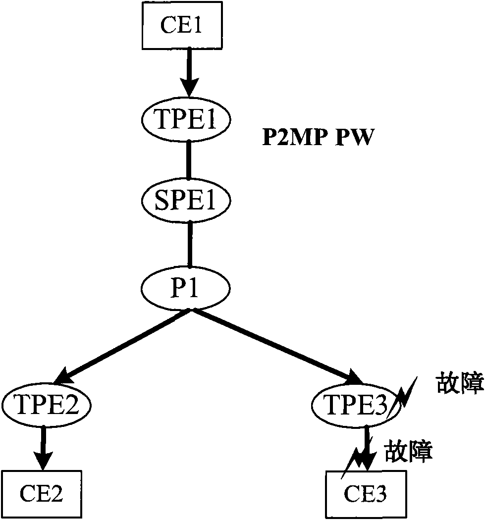
[0120] In this example, the protection of a single-segment P2MP PW is involved. For a single-segment P2MP PW, the ingress PE node is the switching node and is also the upstream PE node of the egress PE.
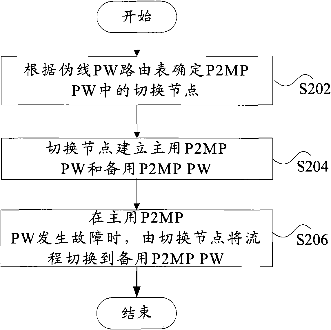
[0121] Picture 11 It is a flowchart of the implementation method of P2MP SS-PW export PE protection in Example 1 of the embodiment of the present invention, such as Picture 11 As shown, the method includes the following steps S1101 to S1108:
[0122] Step S1101, the exit node configures AII and Priority.
[0123] The NLRI fields in the MP_REACH_NLRI and MP_UNREACH_NLRI attributes in the BGP UPDATE messages need to be extended to carry the priority of two bits. Among them, 00 has the highest priority, and the following are 01, 10, 11 in sequence; see Table 1 for the extension of the NLRI field.
[0124] The dual-homing egress node is configured with the same AII and different priorities.
[0125] for Figure 5 The shown P2MP SS-PW protects the network, PE1 is configured with AII11, an...
example 2
[0145] This example involves the protection of multi-segment P2MP MS-PW. The upstream node of the egress PE is the switching node. Figure 7 It is a schematic diagram of P2MP MS-PW export PE protection in Example 2 according to the embodiment of the present invention.
[0146] Picture 12 It is a flowchart of the method for implementing egress PE protection of P2MP MS-PW in Example 2 of the embodiment of the present invention, such as Picture 12 As shown, the method includes the following steps S1201 to S1209:
[0147] In step S1201, the exit node configures AII and Priority.
[0148] The NLRI fields in the MP_REACH_NLRI and MP_UNREACH_NLRI attributes in BGP UPDATE messages need to be extended to carry the priority of two bits. Among them, 00 has the highest priority, and the following are 01, 10, 11 in sequence; see Table 1 for the extension of the NLRI field .
[0149] The dual-homing egress node is configured with the same AII and different priorities.
[0150] for Figure 7 The sh...
example 3
[0170] In this example, the protection of multi-segment P2MP MS-PW is involved, and the network structure is shown in Picture 9 , Picture 9 It is a schematic diagram of P2MP MS-PW export PE protection in Example 3 according to the embodiment of the present invention.
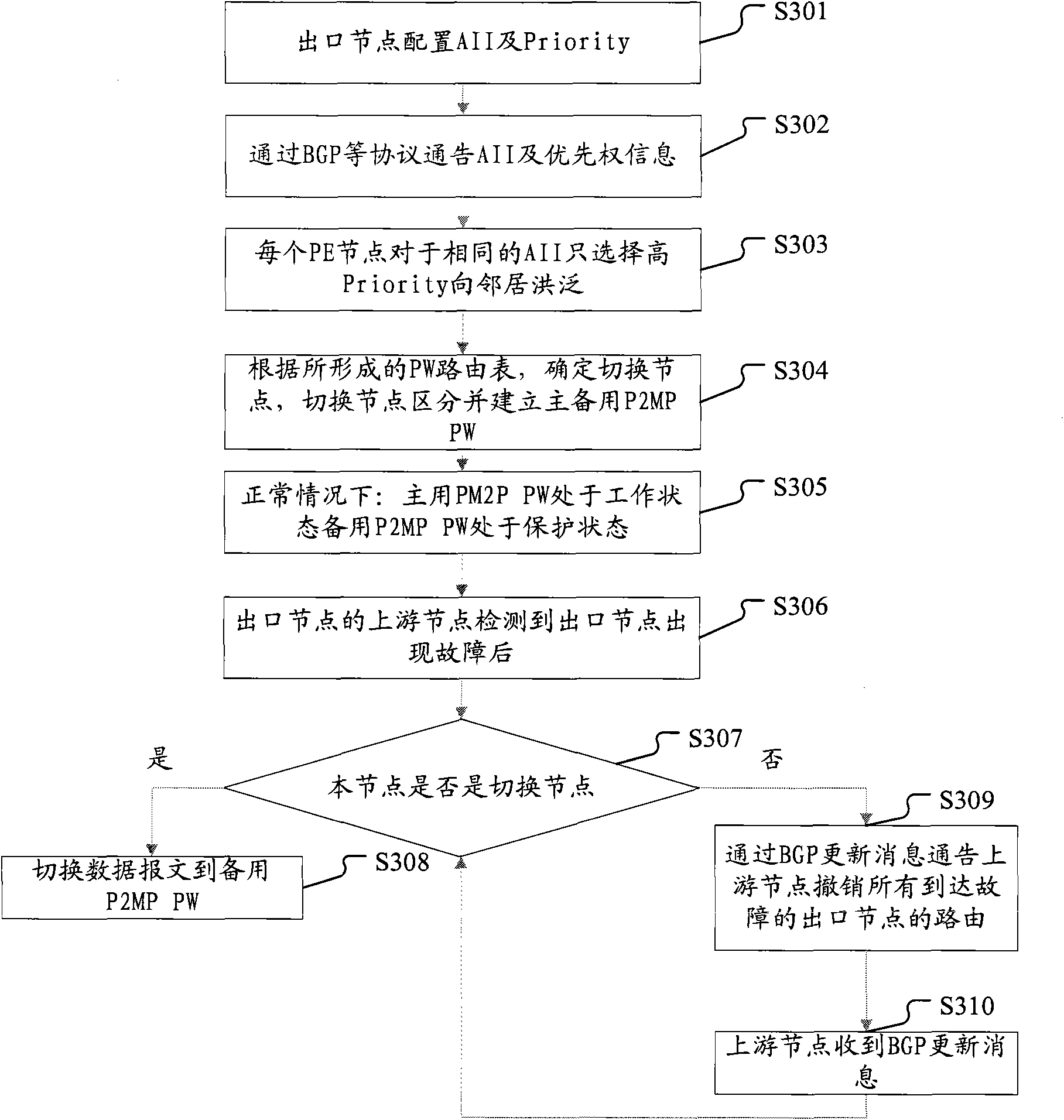
[0171] Figure 13 It is a flowchart of the method for implementing egress PE protection of P2MP MS-PW in Example 3 of the embodiment of the present invention, such as Figure 13 As shown, the method includes the following steps S1301 to S1311:
[0172] In step S1301, the exit node configures AII and Priority.
[0173] The NLRI fields in the MP_REACH_NLRI and MP_UNREACH_NLRI attributes in the BGP UPDATE messages need to be extended to carry the priority of two bits. 00 has the highest priority. The following are 01, 10, and 11 in sequence; see Table 1 for the extension of the NLRI field.
[0174] The dual-homing egress node is configured with the same AII and different priorities.
[0175] for Picture 9 In the network s...
PUM
 Abstract
Description
Claims
Application Information