

Camera system and image forming apparatus
A camera and imaging device technology, applied in the field of imaging equipment
- Summary
- Abstract
- Description
- Claims
- Application Information
AI Technical Summary
Problems solved by technology
Method used
Image

Examples
no. 1 example
[0093] refer to Figure 4 Turning to FIG. 8 , a method of calculating a position of the focusing lens 104 at which the contrast of an object image is maximized according to an embodiment of the present invention will be described.
[0094] Figure 4 Scan lines in region e8 according to an embodiment of the invention are shown.
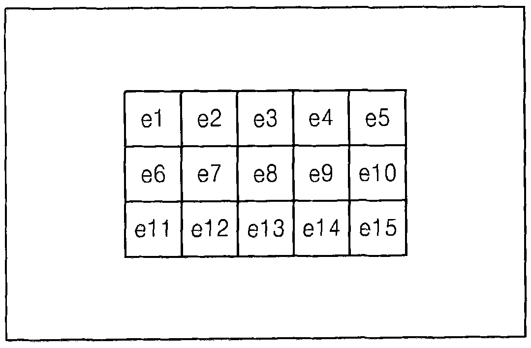
[0095] Regarding the area e8, that is, located at image 3 An AF area in the center of a plurality of AF areas on the shooting screen, an area e8 includes a plurality of scan lines AFareaL8[1] to AFareaL8[a]. According to the present embodiment, a case where AF detection is performed on the area e8 is exemplified.
[0096] Lens operation
[0097] Figure 5 is a timing chart of the AF operation of the lens 100 according to the embodiment of the present invention.
[0098] The lens controller 110 having a timer function resets the first timer 111 according to a command from the camera controller 209 so that the first timer 111 has the same time r...
no. 2 example
[0129] refer to Figure 9 to Figure 1 2. A method of calculating the position of the focusing lens 104 according to an embodiment of the present invention will be described.
[0130] Figure 9 Scan lines in the region e15 according to an embodiment of the present invention are shown.
[0131] Regarding area e15, that is, located in image 3 The AF area of the lower right part of the multiple AF areas of the shooting screen, the area e15 includes a plurality of scan lines AFareaL15[1] to AFareaL15[a]. According to the present embodiment, a case where AF detection is performed on the area e15 is shown as an example.
[0132] Lens operation
[0133] Figure 10 is a timing chart of the AF operation of the lens 100 according to the embodiment of the present invention.
[0134] The lens controller 110 receives time measurement period information from the camera controller 209, and sets the time measurement period of the first timer 111 according to the time measurement per...
no. 3 example
[0161] refer to Figure 13 to Figure 1 5. A method of calculating the position of the focusing lens 104 according to another embodiment of the present invention will be described. According to the present embodiment, a time period between a plurality of time points of intermediate time points of AF detection in the AF area is used as a time measurement period for sharing information in the main body unit 200 and the lens 100 . and image 3 As in the case of , AF detection is performed with respect to the area e8 (ie, the AF area located at the center of the plurality of AF areas on the shooting screen).
[0162] The second timer 228 included in the camera controller 209 operates as a predetermined base clock, and has timing information on time periods between a plurality of time points of intermediate time points of AF detection in the AF area. However, the camera controller 209 does not continuously transmit timing information to the lens 100, but transmits fps information ...
PUM
 Abstract
Description
Claims
Application Information