
Cooling plate arrangement and method for installing cooling plates in a metallurgical furnace

A technology for cooling plates and metallurgical furnaces, applied to furnace cooling devices, furnaces, furnace components, etc., can solve problems such as erosion, backfill concrete erosion, and uneven cooling plates, and achieve the effects of prolonging life and avoiding uneven erosion

Inactive Publication Date: 2011-05-11
PAUL WURTH SA
View PDF8 Cites 0 Cited by
  • Summary
  • Abstract
  • Description
  • Claims
  • Application Information

AI Technical Summary

Problems solved by technology

In practice, however, furnaces occasionally also work without this protective layer, which first of all leads to erosion of the backfill concrete in the gap
These gaps thus lead to a markedly uneven erosion of the cooling plate

Method used


Image

  • Cooling plate arrangement and method for installing cooling plates in a metallurgical furnace
  • Cooling plate arrangement and method for installing cooling plates in a metallurgical furnace
  • Cooling plate arrangement and method for installing cooling plates in a metallurgical furnace

Examples


Embodiment Construction

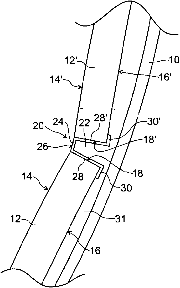
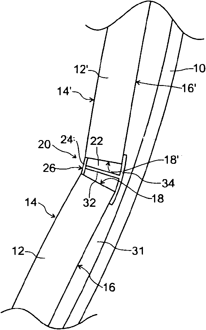
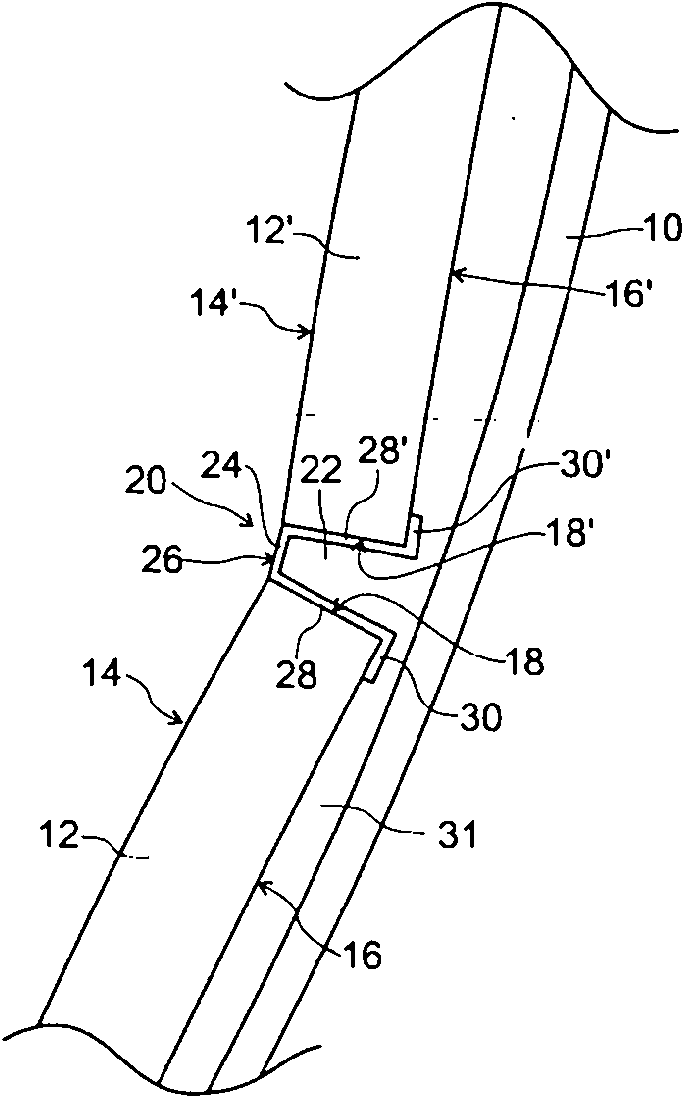
[0024] Cooling plates are used to cover the inner walls of the shell of metallurgical furnaces, such as blast furnaces or electric arc furnaces. The purpose of this cooling plate is to form: (1) a thermal protection screen between the interior of the furnace and the outer shell; Anchoring device.

[0025] The figure shows a cross-sectional view of a part of such an inner wall 10 seen from above. In front of the inner wall 10 is mounted a cooling plate arrangement comprising a plurality of cooling plates 12, 12'. The figures partially show the first cooling plate 12 and the second cooling plate 12'. Each cooling plate 12 , 12 ′ has a lath-shaped body made, for example, of a cast or forged body of copper, copper alloy or steel. This slatted body has: a front face 14, 14' (also called hot face), which will face the interior of the furnace; and a rear face 16, 16' (also called cold face), which will face the inner wall 10 inner surfaces. The slatted body is generally in the f...


PUM


Abstract

The present invention proposes a gap-filler insert (20) for use with cooling plates (12, 12') for a metallurgical furnace, the cooling plates (12, 12') having a front face (14, 14') directed towards the interior of the furnace, an opposite rear face (16, 16') directed towards a furnace wall (10) of the furnace and four edge faces (18, 18'). In accordance with an aspect of the present invention, the gap-filler insert (20) comprises a metal front plate (24) with a front side (24) facing the interior of the furnace and anchoring means (28, 28', 30, 30', 32, 34) for mounting the front plate (24) between two neighboring cooling plates (12, 12') in such a way that the front plate (24) extends between the edge faces (18, 18') of both cooling plates (12, 12'), and that the front side (26) of the front plate (24) is flush with the front faces (14, 14') of both cooling plates (12, 12').

Description

technical field [0001] The present invention generally relates to a cooling plate arrangement in a metallurgical furnace. The invention further relates to a method of installing a cooling plate arrangement in a metallurgical furnace. Background technique [0002] Cooling plates (also called staves) for metallurgical furnaces are well known in the art. These cooling plates are used to cover the inner wall of the shell of a metallurgical furnace (eg, a blast furnace or an electric arc furnace) to provide: (1) a heat evacuating protection screen between the interior of the furnace and the outer shell; and (2) Anchoring device for refractory brick lining, refractory shotcreting or growth in furnaces during processing. Originally, cooling plates were cast iron plates with cooling tubes cast into them. As an alternative to cast iron staves, copper staves have been developed. Today, most cooling plates used in metallurgical furnaces are made of copper, copper alloys or (more re...

Claims


Application Information

Patent Timeline
Patent Type & Authority Applications(China)
IPC IPC(8): F27D1/12F27D1/14F27D1/16
CPCF27D1/145F27D1/1678F27D1/12F27D1/14F27D1/16
Inventor 尼古拉·马焦利保罗·托克尔特尼古拉·穆塞尔柯劳德·普莱梅尔丁
Owner PAUL WURTH SA
Learn More