
Drainage, filtration, and electricity generating systems and methods

Inactive Publication Date: 2010-12-30
PATENTS INNOVATIONS
View PDF9 Cites 25 Cited by
  • Summary
  • Abstract
  • Description
  • Claims
  • Application Information

AI Technical Summary

Benefits of technology

[0007]Still another example reason why drainage systems are used is to slow (and sometimes even stop) erosion that may prematurely damage a newly constructed building or surrounding structures. The threat of accelerated erosion may be a large concern in areas where there is loose-fill dirt, clay, sand, etc. In such cases, drainage systems may help to remove water penetrating a soil mass or to lower the existing ground water table, e.g., so that water is led away and / or allowed to permeate the ground at an appropriate rate (e.g., that slows or stops erosion).
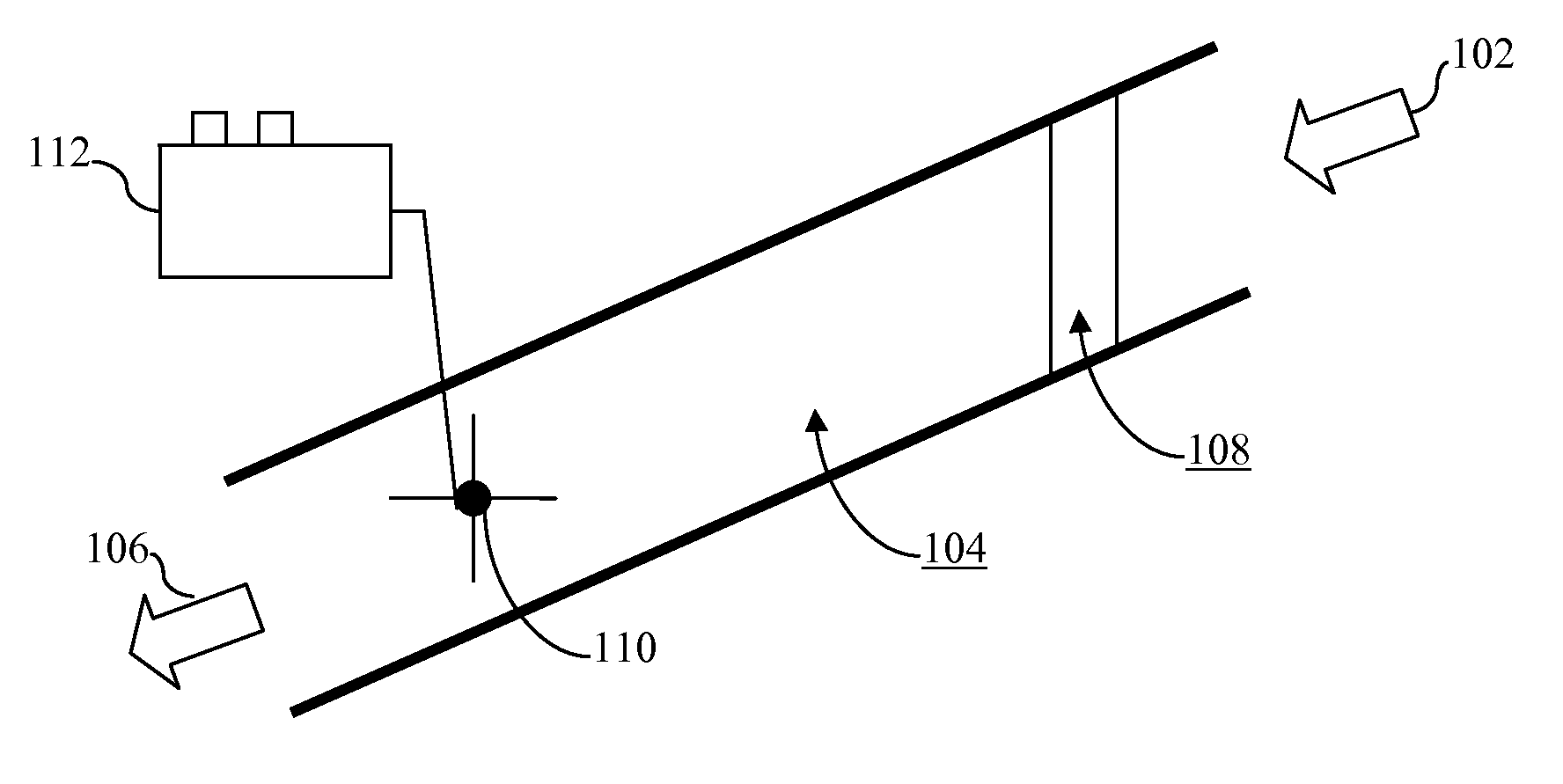
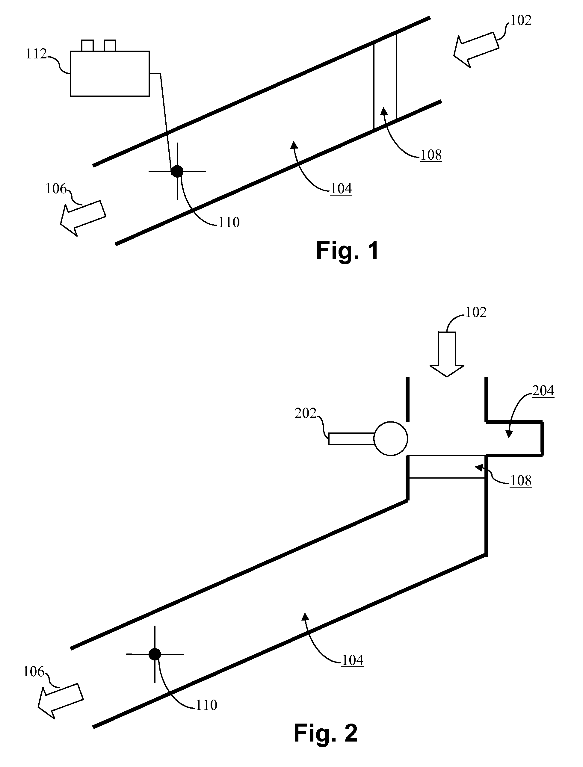
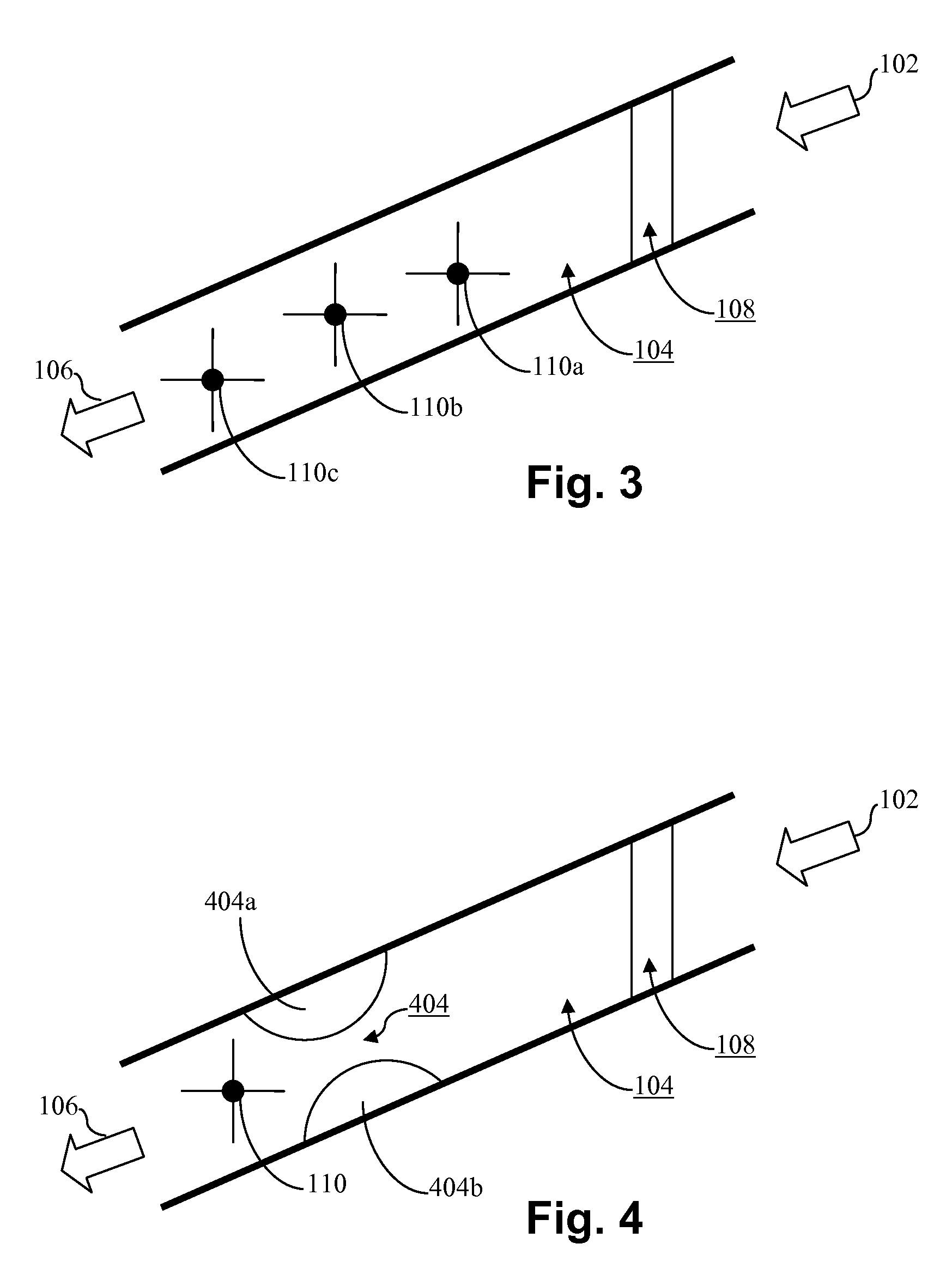
[0010]Thus, one aspect of certain example embodiments of this invention pertains to an environmentally sound way of producing “green” energy in connection with drainage systems that already are designed to help protect, and / or reduce the impact on, the surrounding environment. Certain example embodiments thus may produce hydroelectric power by causing drained water to turn one or more turbines located in a drainage system.
[0014]According to certain example embodiments, a plurality of elements may be provided upstream of the at least one turbine and downstream of the filtration subsystem. Adjacent elements may define constriction locations therebetween to help accelerate the flow of fluids passing therethrough.

Problems solved by technology

However, this often is not possible after the construction is complete.
Thus, runoff in the form of these and / or other waste products also may become problematic once construction is complete.
At both time periods (e.g., during construction and after construction), the potential environmental impact is large, as the runoff could contaminate the water table, nearby waterways, etc.
Without this storage function, the liquids could overwhelm the local streams when a storm comes, etc.
In addition to possibly overwhelming streams, the runoff could include fuel, oil, grease, dirt, etc., resulting from the day-to-day usage of the site.
The threat of accelerated erosion may be a large concern in areas where there is loose-fill dirt, clay, sand, etc.
Although drainage systems have been in place for some years and used to help address these and / or other problem areas, the inventor of the instant application has realized that the flowing channeled water itself represents a potentially vast and untapped source of kinetic energy.

Method used


Image

  • Drainage, filtration, and electricity generating systems and methods
  • Drainage, filtration, and electricity generating systems and methods
  • Drainage, filtration, and electricity generating systems and methods

Examples


Embodiment Construction

[0023]Certain example embodiments of this invention relate to an environmentally sound way of producing “green” energy in connection with drainage systems that already are designed to help protect, and / or reduce the impact on, the surrounding environment. More particularly, certain example embodiments thus may produce hydroelectric power by causing drained water to turn one or more turbines located in a drainage system. In certain example instances, drainage is captured by a drainage system. That drainage is then filtered in connection with a filtration subsystem. The filtered liquid then may be fed into piping so as to encounter one or more turbines located downstream of the filtration subsystem. Blades of the one or more turbines may be caused to turn, thereby generating hydroelectric power that can be stored or used in any of a variety of applications.

[0024]Referring now more particularly to the drawings in which like reference numerals indicate like parts throughout the several ...


PUM

PropertyMeasurementUnit
Flow rateaaaaaaaaaa
Areaaaaaaaaaaa

Abstract

Certain example embodiments of this invention relate to techniques for collecting run-off and / or draining water from commercial or residential sites, filtering out the liquid, and using the filtered liquid to engage one or more turbines to generate electricity. In certain example embodiments, the one or more turbines are located downstream of filtration, grease-collection, and / or other purification devices. The electricity generated by the one or more turbines may be stored in batteries, serve as a power source for an active drainage / filtration system, used for other activities in or around the site, etc. In certain example embodiments, elements (such as sidewalls, vanes, and / or the like) may be provided upstream of the at least one turbine and downstream of the filtration subsystem, with adjacent elements defining constriction locations therebetween to help accelerate the flow of fluids passing therethrough.

Description

FIELD OF THE INVENTION[0001]Certain example embodiments of this invention relate to systems and / or methods for drainage, filtration, and / or electricity generation. More particularly, certain example embodiments of this invention relate to techniques for collecting run-off and / or draining water from commercial or residential sites, filtering out the liquid, and using the filtered liquid to engage one or more turbines to generate electricity. In certain example embodiments, the one or more turbines are located downstream of filtration, grease-collection, and / or other purification devices. The electricity generated by the one or more turbines may be stored in batteries, serve as a power source for an active drainage / filtration system, and / or used for other activities in or around the site.BACKGROUND AND SUMMARY OF EXAMPLE EMBODIMENTS OF THE INVENTION[0002]The use of drainage systems in connection with commercial and residential sites is known. Indeed, many states throughout the United ...

Claims


Application Information

Patent Timeline
IPC IPC(8): F03B13/08C02F1/00F04B17/03B01D35/26H05K13/00B01D37/00H02J7/34
CPCC02F2103/001F03B13/00F04B53/04Y10T29/49002H02J3/32Y02B10/50F05B2220/60
Inventor MARDIROSSIAN, ARIS
Owner PATENTS INNOVATIONS
Learn More