Oil decantation system for an internal combustion engine

Active Publication Date: 2020-12-10
NOVARES FRANCE
View PDF0 Cites 0 Cited by
  • Summary
  • Abstract
  • Description
  • Claims
  • Application Information

AI Technical Summary

Benefits of technology

[0012]In this technical context, an object of the invention is to provide a decantation system improving the separation performances of oil droplets present in a blow-by gas. The invention concerns an oil decantation system for an internal combustion engine compris

Problems solved by technology

These gases are produced during normal operation of the engine; indeed, gases escape from the combustion chambers by passing along the piston rings and leak into the crankcase.
The introduction of the blow-by gas loaded with oil to burn them in the cylinders increases the

Method used


Image

  • Oil decantation system for an internal combustion engine
  • Oil decantation system for an internal combustion engine
  • Oil decantation system for an internal combustion engine

Examples


Example

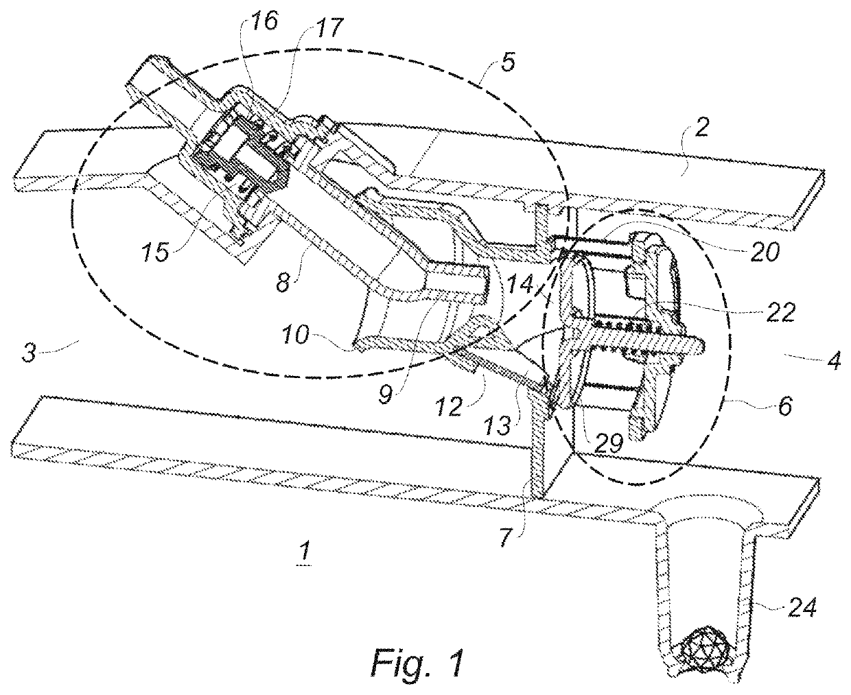
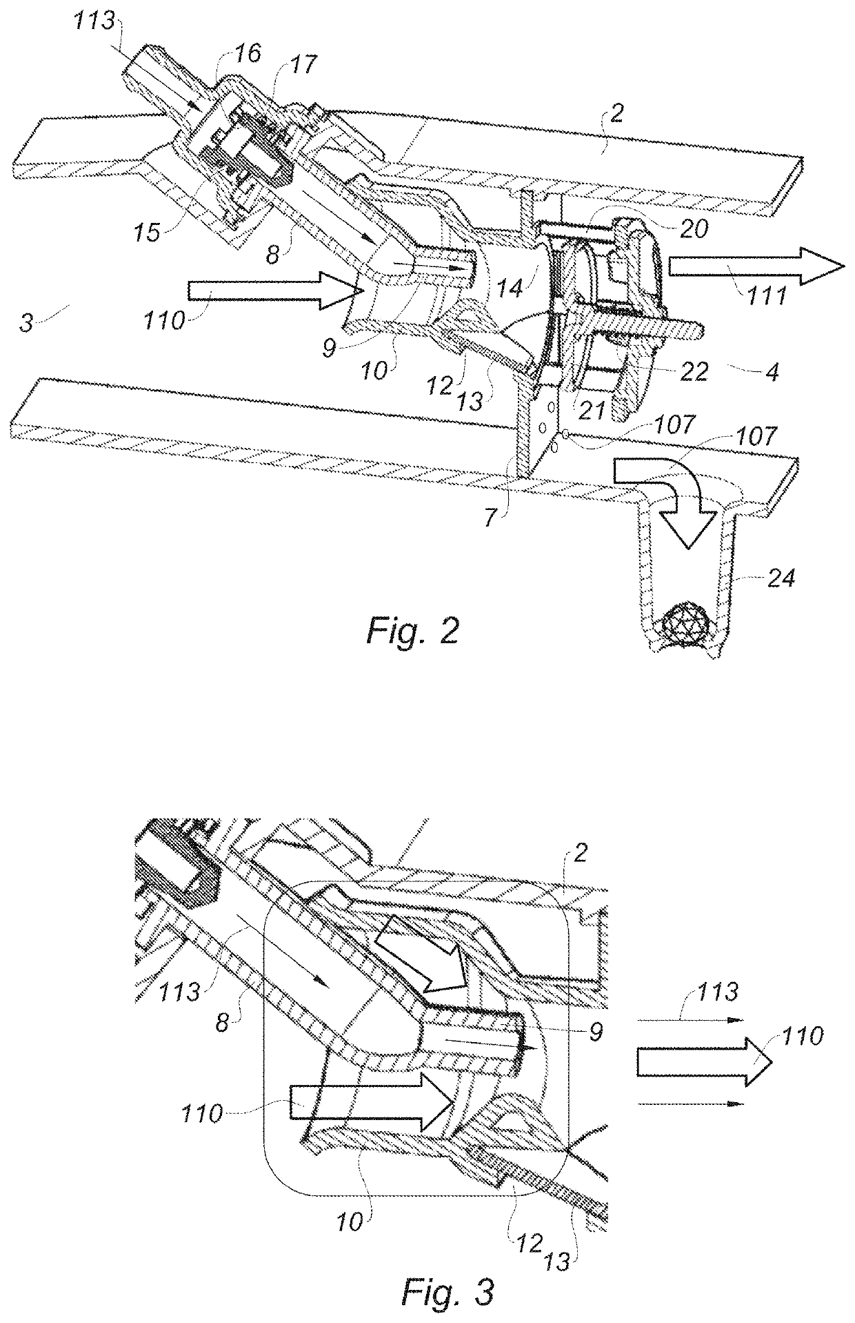
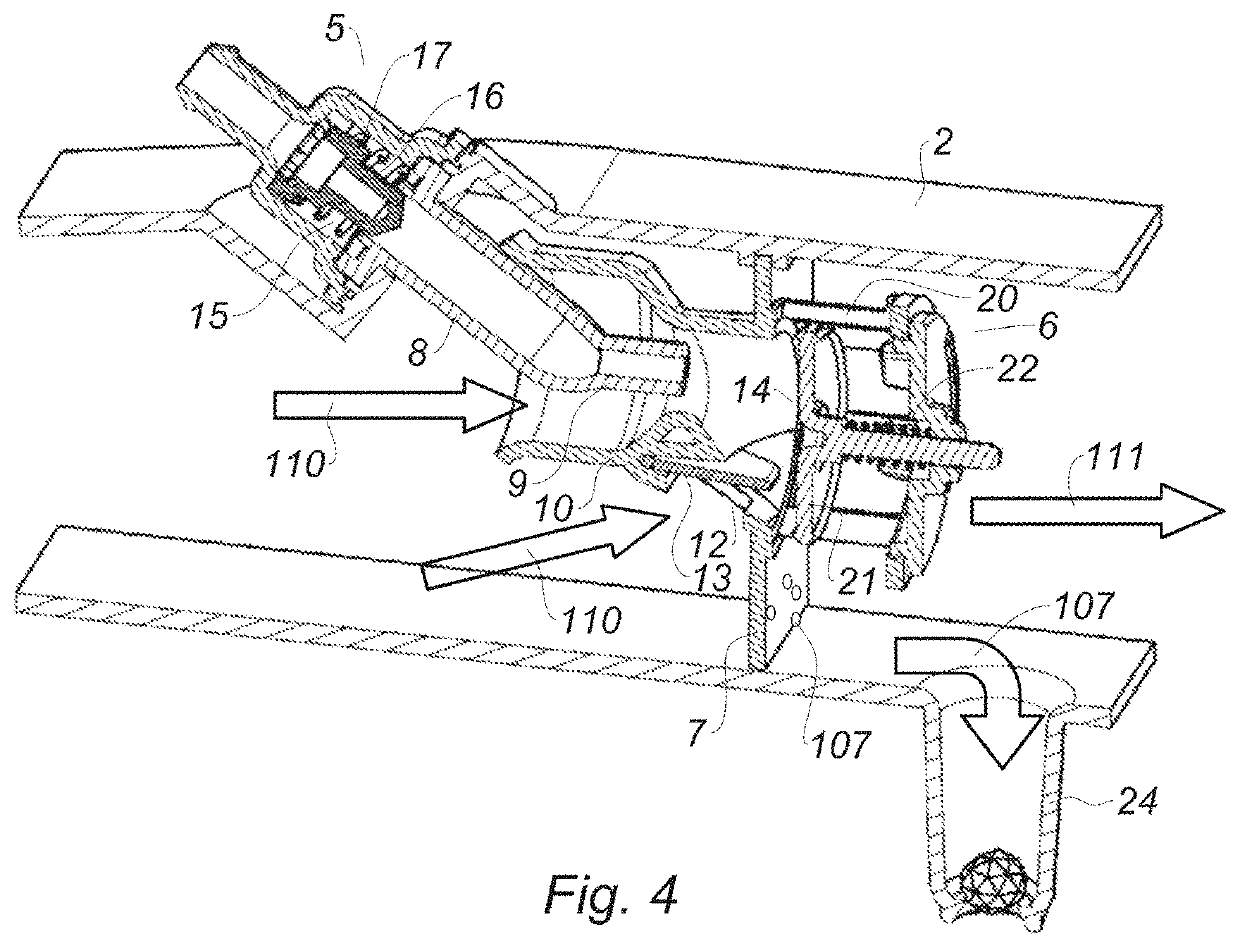
[0033]Schematically, an internal combustion engine 100 as represented in FIG. 10 comprises in particular a cylinder 101 within which a piston 102 moves, a crankcase 103 within which oil 106 splashes, and a suction duct 104. During the operation of the engine, burnt gases 105 infiltrate into the oil pan 103 passing between the cylinder 101 and the piston 102 throughout the piston's rings. Their evacuation causes a gas flow called blow-by gas 110 loaded with oil droplets collected during splashing in the oil 106.

[0034]The engine 100 is equipped with an oil separator device 1 according to the invention.

[0035]The blow-by gases 110 are routed at the inlet of the oil separator device 1 according to the invention, the latter allowing freeing the flow of the blow-by gas 110 from the oil droplets contained therein. The captured oil droplets 107 are collected and routed towards the oil pan 103 for recycling. The gaseous flow 111 freed from the oil droplets is evacuated into the air suction du...


PUM

PropertyMeasurementUnit
Flow rateaaaaaaaaaa
Areaaaaaaaaaaa
Gravityaaaaaaaaaa

Abstract

The invention relates to an oil decantation system (1) comprising: (i) a separator device (6) designed to trap the oil droplets (107) that are present in a flow of a blow-by gas (110); and (ii) a jet pump (5) positioned upstream of the separator device (6) and designed to accelerate and draw the flow of the blow-by gas (110) before it enters said separator device (6).

Description

CROSS REFERENCE TO RELATED APPLICATIONS[0001]This application is a National Stage of PCT Application No. PCT / FR2018 / 053092 filed on Dec. 3, 2018, which claims priority to French patent application FR 17 / 61644 filed on Dec. 5, 2017 the contents each of which are incorporated herein by reference thereto.TECHNICAL FIELD[0002]The present invention concerns a decantation system for an internal combustion engine.BACKGROUND[0003]During its operation, an internal combustion engine produces leakage gases, called «blow-by» gases or «crankcase» gases, that is to say gases that are trapped in the crankcase. These gases are produced during normal operation of the engine; indeed, gases escape from the combustion chambers by passing along the piston rings and leak into the crankcase. They pass through the lower crankcase where they are loaded with oil droplets.[0004]Blow-by gases must be evacuated from the crankcase so as not to excessively pressurize the latter.[0005]As blow-by gases are loaded w...

Claims


Application Information

Patent Timeline
IPC IPC(8): F01M13/04F01M13/02F01M13/00B01D45/08
CPCF01M13/0011F01M2013/026B01D45/08F01M13/028F01M13/04B01D45/04B01D46/10F01M13/021F01M2013/0044
Inventor MAESEELE, CHRISTOPHEPECH, CHRISTOPHEDEMANGEOT, JEROME
Owner NOVARES FRANCE
Why Eureka
Try Eureka