Method for Burning of Gaseous and Burner

Active Publication Date: 2009-09-03
NORWEGIAN UNIVERSITY OF SCIENCE AND TECHNOLOGY (NTNU)
View PDF17 Cites 76 Cited by
  • Summary
  • Abstract
  • Description
  • Claims
  • Application Information

AI Technical Summary

Benefits of technology

[0020]Primary fuel gas is injected into the combustion air and very well mixed by the turbulent flow while passing over the burner head where the flow-area cross section is decreased while flowing downstream. The reduction in cross section has the effect of accelerating the flow.
[0021]Secondary fuel is supplied creating a flame stabilization zone in front of the burner head. The said flame stabilization zone allows the main mixture of primary fuel and combustion air flowin

Problems solved by technology

This is due to the turbulence generated by the air flow through and over the perforated divergent cone.
The mi

Method used


Image

  • Method for Burning of Gaseous and Burner
  • Method for Burning of Gaseous and Burner
  • Method for Burning of Gaseous and Burner

Examples


example 1

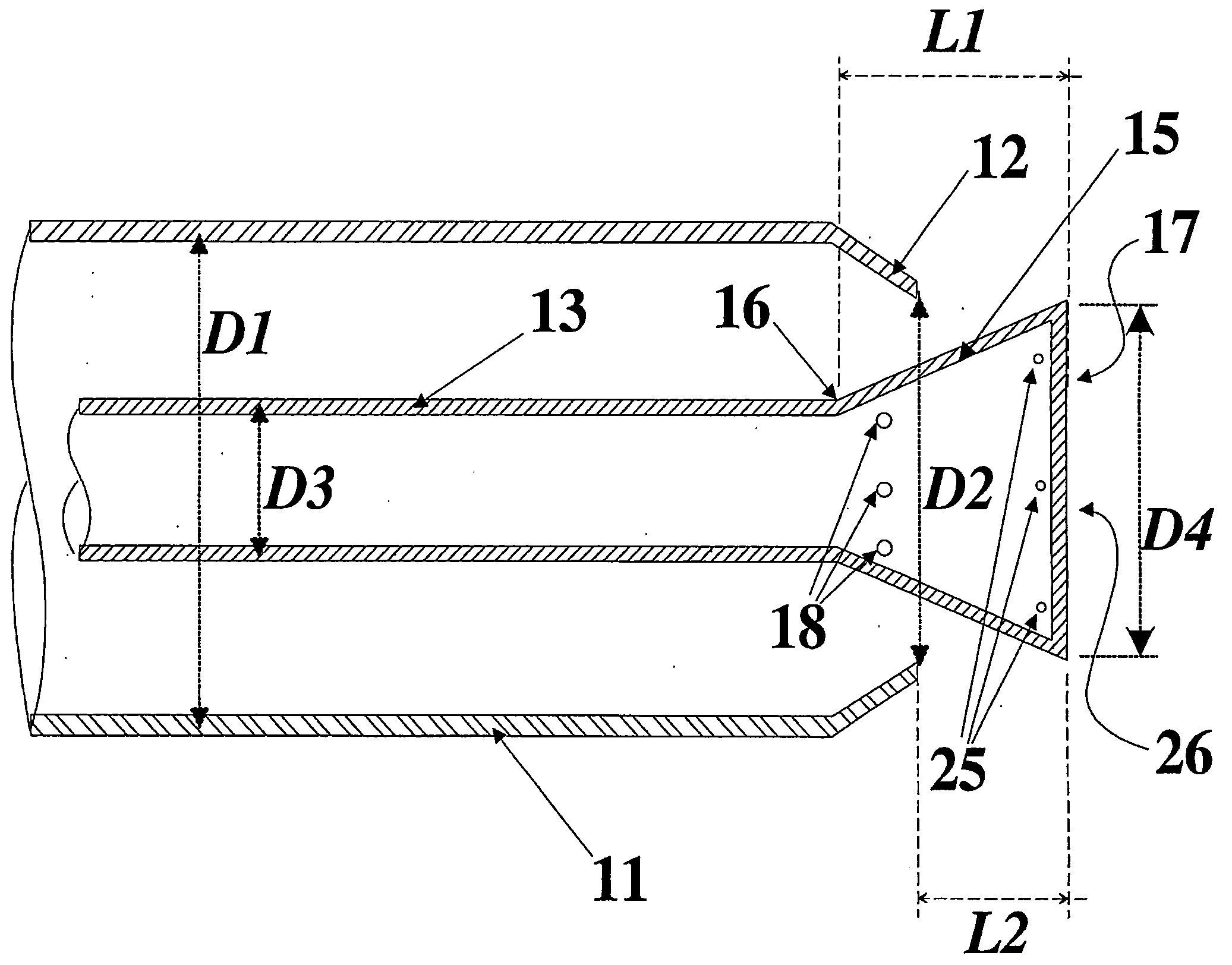
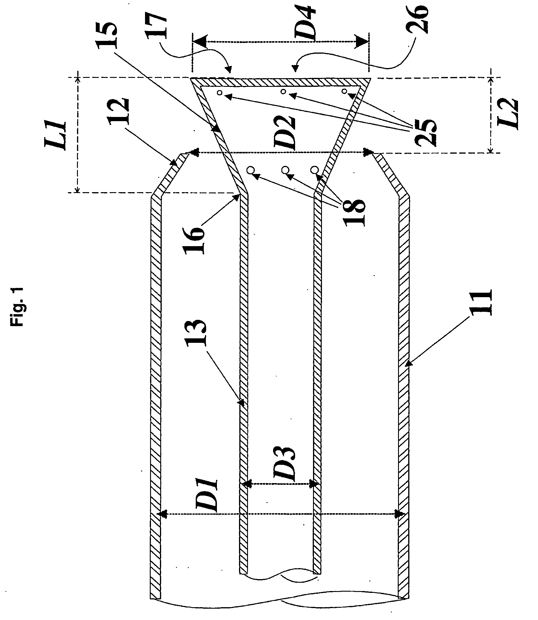
[0043]The burner configuration described in this example has been applied for propane as gaseous fuel. In this example, eight primary orifices 18 with a diameter of 3 mm are arranged in a circular row around the circumference of the narrow beginning 16) of the burner head 15. The outer tube 11 diameter D1 is 100 mm and the conical converging section 12 has a minimum diameter D2 of 75 mm. The inner gaseous fuel tube 13 has an outer diameter D3 of 30 mm, while the burner head 15 has a maximum diameter D4 of 70 mm and a length L1 of 50 mm. The burner head 15 is positioned in such a way that the distance L2 from the end of the conical converging section 12 to the end of the burner head 15 is 25 mm.

example 2

[0044]The burner configuration described in this example has been applied for natural gas (82.35% methane, 13.83% ethane, 1.10% butane, 1.13% nitrogen, 1.49% carbon monoxide and 0.10% heavier hydrocarbons) as gaseous fuel. The burner configuration is as described above, but some dimensions have been changed.

[0045]In this example, eight primary orifices 18 with a diameter of 4 mm are arranged in a circular row around the circumference of the narrow beginning 16 of the burner head 15. The outer tube 11 diameter D1 is 100 mm and the conical converging section 12 has a minimum diameter D2 of 75 mm. The inner gaseous fuel tube 13 has an outer diameter D3 of 30 mm, while the burner head 15 has a maximum diameter D4 of 70 mm and a length L1 of 50 mm. The burner head 15 is positioned in such a way that the distance L2 from the end of the conical converging section 12 to the end of the burner head 15 is 32 mm.

example 3

[0046]The burner configuration described in this example has been applied for propane as gaseous fuel. The burner configuration is as described above, but the dimensions have been changed.

[0047]In this example, eight primary orifices 18 with a diameter of 4.1 mm are arranged in a circular row around the circumference of the narrow beginning 16 of the burner head 15. The outer tube 11 diameter D1 is 136 mm and the conical converging section 12 has a minimum diameter D2 of 102 mm. The inner gaseous fuel tube 13 has an outer diameter D3 of 42 mm, while the burner head 15 has a maximum diameter D4 of 96 mm and a length L1 of 68 mm. The burner head 15 is positioned in such a way that the distance L2 from the end of the conical converging section 12 to the end of the burner head 15 is 34 mm.

[0048]These dimensions from examples 1 to 3 are summarized in Table 1. Emissions of NOx and CO measured from the burners described in example 1 to 3 is shown in FIGS. 4 to 6, respectively.

TABLE 1Exampl...


PUM


Abstract

A method for burning gas in a burner, including leading the gas through an inner fuel tube (13) and introduction of combustion air through an annular space surrounding the inner fuel tube. This space forms of an outer tube (11) terminated by a conically converging section, wherein the end of the inner fuel tube forms a burner head (15). The major part of the primary gas is introduced into the upstream end of the burner head, to go into the combustion air that flows past the burner head, whereas a smaller part of a secondary gas is introduced into the free end of the burner head (15) and into the constricted part of the annular channel that surrounds the burner head. The gas flow is accelerated past the burner head due to the reducing cross section and is burned downstream in relation to the burning head, wherein the mixture has properties that reduces the formation of Nox at the same time as the combustion becomes complete. It is also described a burner for performing this method.

Description

[0001]The invention relates to a method for burning gaseous fuel as described in the introduction to claim 1, and a burner as described in the introduction to claim 3, with premixing and recirculation, for the combustion of gaseous fuel.BACKGROUND OF THE INVENTION[0002]Nitrogen oxides (denoted NOx) consist mainly of NO and NO2 and are a main component in the formation of ground-level ozone, but can also react to form nitrate particles and acid aerosols, which can affect human health by causing respiratory problems. Further, NOx contributes to formation of acid rain and global warming. Consequently, reduction of NOx formation has become a major topic in combustion research.NOx Formation Mechanisms[0003]Generally, when using a gaseous fuel, the main pollution components are NOx, with NO as the dominating component. NOx in gas combustion is mainly formed by three mechanisms: the thermal NO mechanism, the prompt NO mechanism and the nitrous oxide (N2O) route to NOx. The different mechan...

Claims


Application Information

Patent Timeline
IPC IPC(8): F23D14/22F23C5/08
CPCF23D14/22F23D2900/00008F23C2201/30F23D14/58
Inventor SPANGELO, OYSTEINSONJU, OTTO KRISTIANSLUNGAARD, TORBJORNDITARANTO, MARIO
Owner NORWEGIAN UNIVERSITY OF SCIENCE AND TECHNOLOGY (NTNU)
Why Eureka
Try Eureka