Method and device for forging a workpiece in bar form

Active Publication Date: 2017-11-09
GFM GMBH
View PDF0 Cites 0 Cited by
  • Summary
  • Abstract
  • Description
  • Claims
  • Application Information

AI Technical Summary

Benefits of technology

[0007]Since, as a result of this measure, the workpiece is supported centrally on both sides of a bending zone and between these central supports is bent out of a position coaxial to the forging axis by forging tools acting radially in relation to the forging axis, transverse loads occur both during the bending of the workpiece out of the forging axis and during the bending thereof back into the forging axis, and these transverse loads lead to shear stresses which are distributed over the cross-section and which ensure a notable grain refinement over the entire cross-section of the workpiece. With the aid of the forging tools used for this purpose, even workpieces having relatively large cross-sectional dimensions can easily be machined in at least one pass.
[0008]Particularly advantageous conditions for improving the grain structure are obtained if the workpiece is subjected to a forging reduction in front of the bending zone in the advancement direction, because the influences of the forging parameters on the crystalline structure of the workpiece can advantageously be used in conjunction with the additional bending-reducing cross-sectional displacement perpendicular to the forging axis. After the grain refinement by bending out the workpiece by means of forging tools, the workpiece can be subjected to a further cross-sectional reduction, which brings about the additional advantage of a precise guidance coaxial to the forging axis. A final finish-machining gives rise to a suitable surface quality. The forging-induced cross-sectional reduction of a workpiece as well as the final finishing forces a workpiece position coaxial to the forging axis, so that the workpiece, during the reduction forging and/or during the finishing, can be supported centrally for the bending deformation without additional measures.
[0009]To carry out a forging method according to the invention, it is possible to start from conventional forging devices with forging tools arranged in pairs opposite one another in relation to the forging axis. It is merely necessary to ensure that the forging tools have, in the region of the bending zone, moulding

Problems solved by technology

However, the possibility of influencing the grain structure by changing these parameters is limited, particularly in terms of achieving a grain structure that is as uniform a

Method used


Image

  • Method and device for forging a workpiece in bar form
  • Method and device for forging a workpiece in bar form
  • Method and device for forging a workpiece in bar form

Examples


Example

WAY OF IMPLEMENTING THE INVENTION

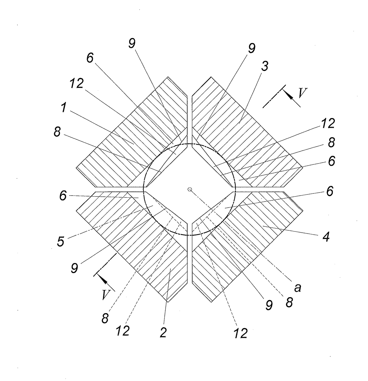
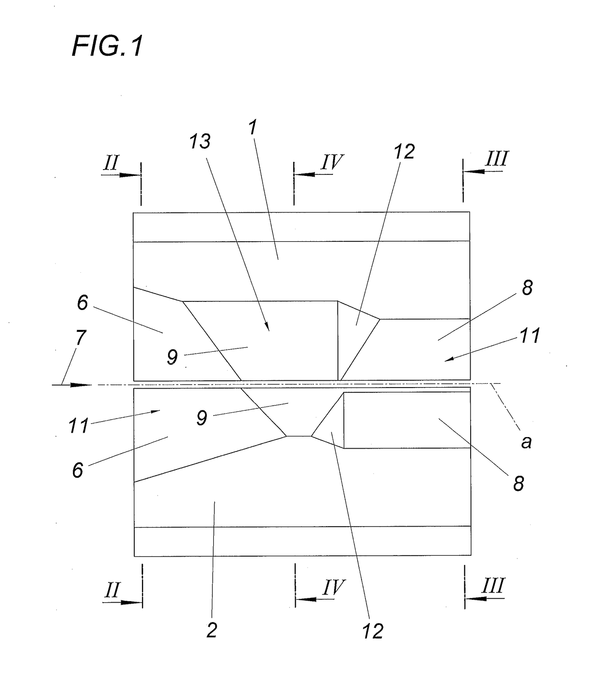
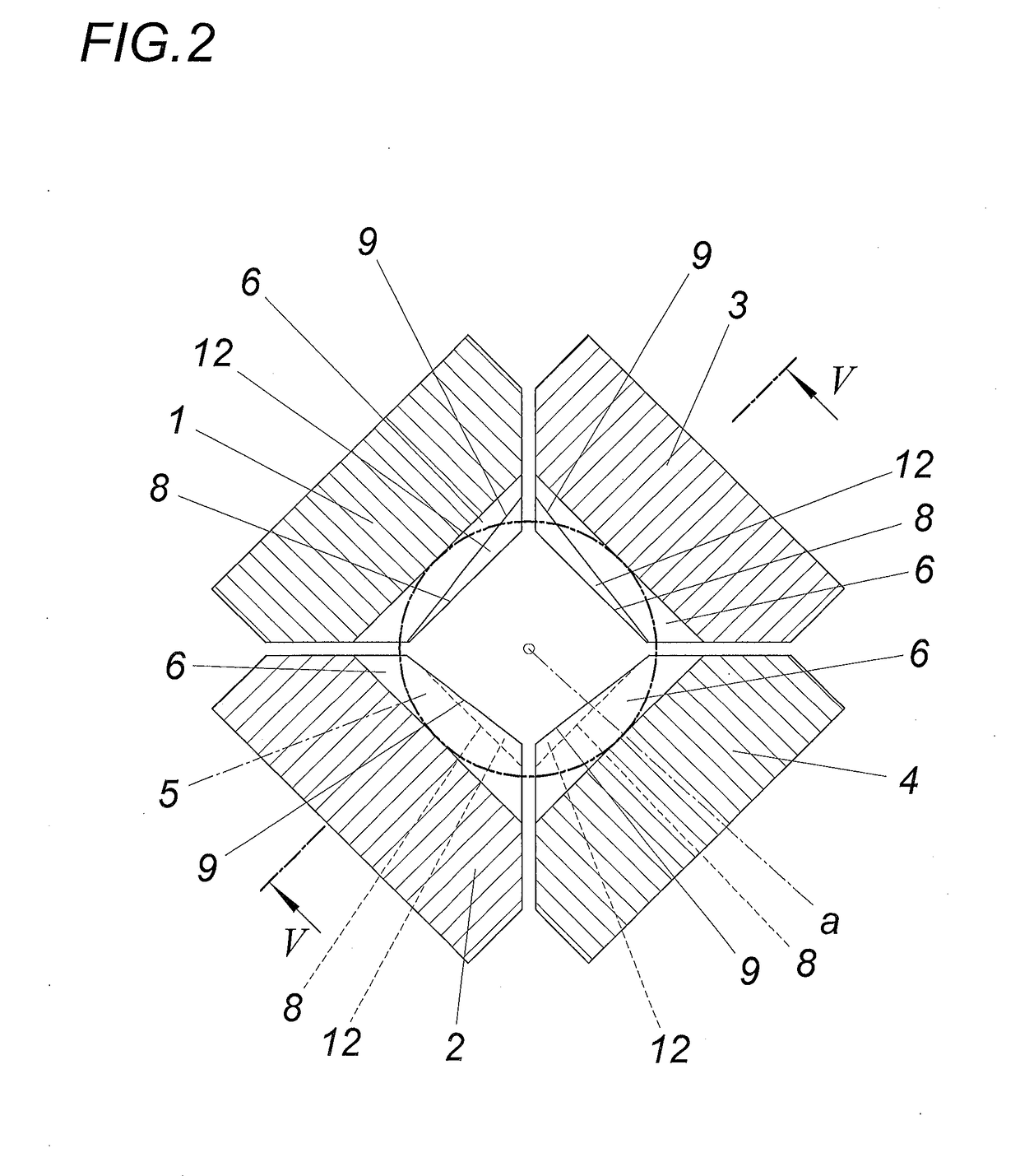
[0019]Of the forging device constructed in a known manner, only the four forging tools 1, 2, 3, 4 are shown in the illustrated exemplary embodiment, said forging tools being arranged in pairs opposite one another and being able to be acted upon radially in relation to a forging axis a, the setting shown forming the mould cavity for a rod-shaped workpiece 5 that is indicated in dash-dotted line. Said forging tools 1, 2, 3, 4 form inlet-side moulding surfaces 6, which create a mould cavity coaxial to the forging axis a and which give rise to a cross-sectional reduction on account of their course being inclined in the advancement direction 7. On the outlet side, moulding surfaces 8 are provided, which likewise define a mould cavity coaxial to the forging axis a and advantageously ensure an additional cross-sectional reduction, which aids the central guidance of the workpiece 5 in the region of the outlet-side moulding surfaces 8. The outlet-side mouldin...


PUM

PropertyMeasurementUnit
Deformation enthalpyaaaaaaaaaa
Reduction potentialaaaaaaaaaa

Abstract

A description is given of a method and a device for forging a rod-shaped workpiece (5) which is deformed with the aid of forging tools (1, 2, 3, 4) in the sense of a cross-sectional displacement perpendicular to the forging axis (a) and is subjected to an axial advancement and possibly a rotation about the forging axis (a) during the pauses in the engagement of the forging tools (1, 2, 3, 4). In order to achieve an advantageous grain refinement, it is proposed that the workpiece (5) is deformed in the sense of the cross-sectional displacement perpendicular to the forging axis (a) in a bending zone (13) between two central supports (11) by means of the forging tools (1, 2, 3, 4) acting on the workpiece (5) radially in relation to the forging axis (a).

Description

TECHNICAL FIELD[0001]The invention relates to a method for forging a rod-shaped workpiece which is deformed with the aid of forging tools in the sense of a cross-sectional displacement perpendicular to the forging axis and is subjected to an axial advancement and possibly a rotation about the forging axis during the pauses in the engagement of the forging tools, and to a device for carrying out the method.PRIOR ART[0002]During the forging of workpieces which are subjected to an axial advancement and possibly a rotation about the forging axis during the pauses in the engagement of the forging tools, not only is a cross-sectional reduction of the workpiece blank achieved by means of the forging tools arranged in pairs opposite one another and acting radially on the workpiece blank, but also the grain structure of the workpiece is improved. The change in the grain structure depends on various forging parameters, such as the forging temperature, the rate of advancement, the size of the ...

Claims


Application Information

Patent Timeline
IPC IPC(8): B21J13/02B21J1/02B21J7/14C21D7/10
CPCB21J13/02C21D7/10B21J7/14B21J1/025B21J5/00C21D7/02
Inventor KOPPENSTEINER, ROBERT
Owner GFM GMBH
Why Eureka
Try Eureka