Method and device for indicating uplink data transmission

A technology for transmitting data and data, which is applied in the field of indicating uplink data transmission, and can solve the problems that the timing relationship cannot be adopted and the timing relationship cannot be applied.

Active Publication Date: 2011-05-18
DATANG MOBILE COMM EQUIP CO LTD
View PDF3 Cites 17 Cited by
  • Summary
  • Abstract
  • Description
  • Claims
  • Application Information

AI Technical Summary

Problems solved by technology

[0024] The disadvantage of the existing technology is: on the backhaul link between the base station and the relay node, the configuration of the uplink and downlink subframes will change in different wireless frames, and LTE Rel-8 (Long Term Technology Evolution Version 8) cannot be used The timing relationship specified in , and the new fixed timing relationship will not be applicable, so it is necessary to instruct the relay node to send uplink data through a dynamic indication method

Method used


Image

  • Method and device for indicating uplink data transmission
  • Method and device for indicating uplink data transmission
  • Method and device for indicating uplink data transmission

Examples


Embodiment Construction

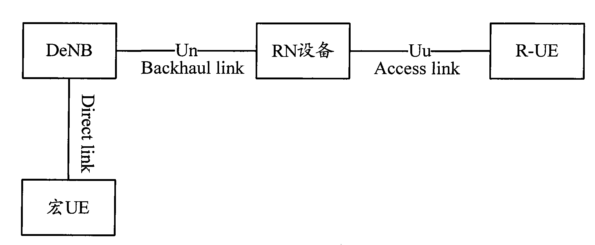
[0063] In the LTE-A system, the introduction of the relay node makes the wireless link between the base station and the user terminal become two hops, and the backhaul link between the base station and the relay node needs to be redesigned. The technical solution will solve the timing problem between the uplink data transmission instruction of the base station and the uplink transmission of the relay node. The specific implementation manner of the present invention will be described below with reference to the accompanying drawings.

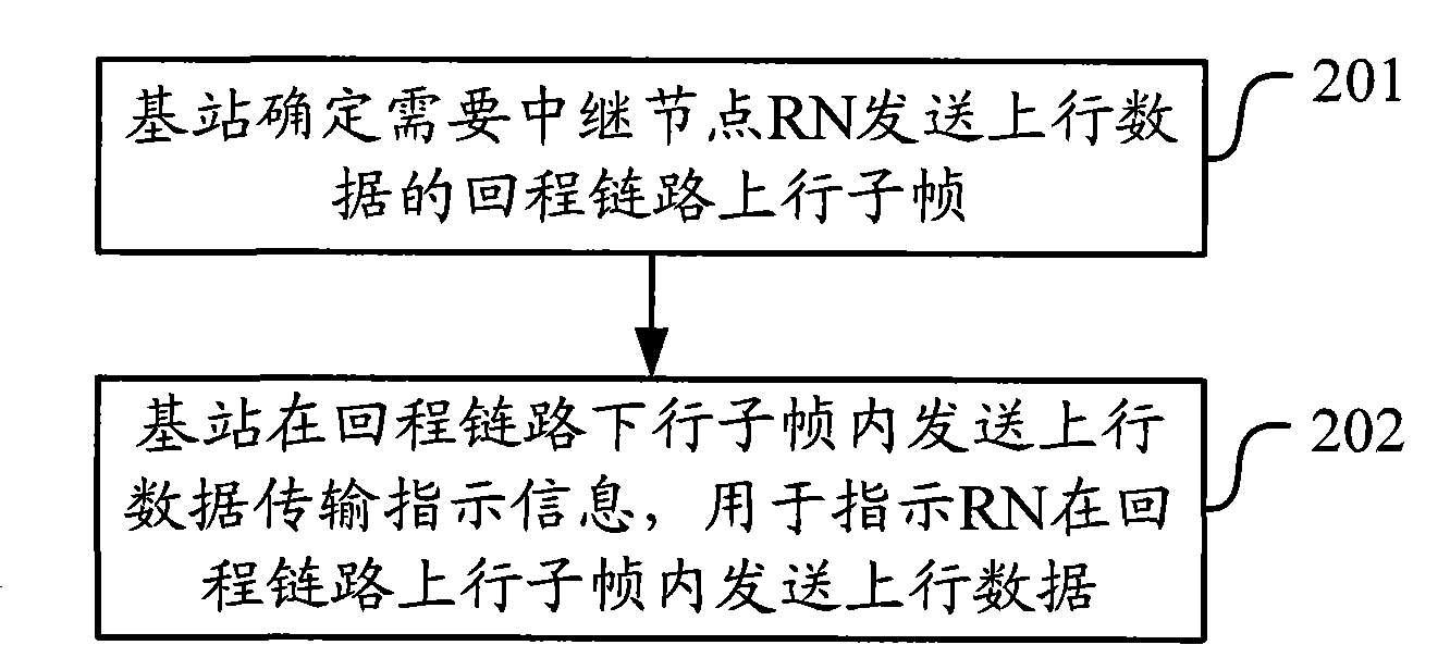
[0064] figure 2 It is a schematic diagram of the implementation process of the method for instructing uplink data transmission, as shown in the figure, the following steps may be included in the uplink instruction:

[0065] Step 201, the base station determines the uplink subframe of the backhaul link in which the relay node RN needs to send uplink data;

[0066] Step 202, the base station sends uplink data transmission instruction information ...


PUM


Abstract

The invention discloses a method and device for indicating uplink data transmission. The method provided by the invention comprises the following steps: a base station determines a backhaul link uplink subframe which needs a trunk node to transmit uplink data; and the base station transmits uplink data transmission indication information, which is used for indicating that the trunk node transmits uplink data in the backhaul link uplink subframe, in the backhaul link downlink subframe. The method and device can be used for dynamically indicating the position of a trunk node transmission relay-physical uplink sharing channel; and when the configuration of the backhaul link subframe is changed, the fixed timing relationship can not adapt to the new subframe timing, but the technical scheme provided by the invention can normally and flexibly indicating the uplink transmission.

Description

technical field [0001] The invention relates to mobile communication technology, in particular to a method and equipment for instructing uplink data transmission. Background technique [0002] (1), after the LTE-A (Long Term Evolution-Advanced, long-term evolution upgrade) system introduces the Relay (relay) node, the following nodes, interfaces and links are defined, figure 1 It is a schematic structural diagram of an LTE-A system according to an embodiment of the present invention, such as figure 1 As shown, the nodes include: [0003] Donor-eNB: eNB (evolved base station) wirelessly connected to RN (relay) equipment, abbreviated as DeNB; [0004] Relay-Node: an entity existing between DeNB and UE, abbreviated as RN device; [0005] Relay-UE: UE that performs data interaction with RN equipment, abbreviated as R-UE; [0006] Macro UE: a UE that directly exchanges data with the DeNB. [0007] Interfaces include: [0008] Un interface: the interface between the RN devic...

Claims


Application Information

Patent Timeline
Patent Type & Authority Applications(China)
IPC IPC(8): H04B7/26H04L1/18
Inventor 张文健潘学明沈祖康肖国军王立波
Owner DATANG MOBILE COMM EQUIP CO LTD
Why Eureka
Try Eureka