Power slide device for vehicle seat

Inactive Publication Date: 2011-05-18
SHIROKI KOGYO CO LTD
View PDF2 Cites 10 Cited by
  • Summary
  • Abstract
  • Description
  • Claims
  • Application Information

AI Technical Summary

Problems solved by technology

[0009] However, there is a problem with the conventional device that when a buckling load is applied to the screw, for example, when a collision occurs, the screw and the load transmission member are actually engaged at one point (within a narrow range) in the axial direction, so the screw generates a large force. Buckling, as a result, cannot obtain sufficient impact resistance

Method used


Image

  • Power slide device for vehicle seat
  • Power slide device for vehicle seat
  • Power slide device for vehicle seat

Examples


Embodiment Construction

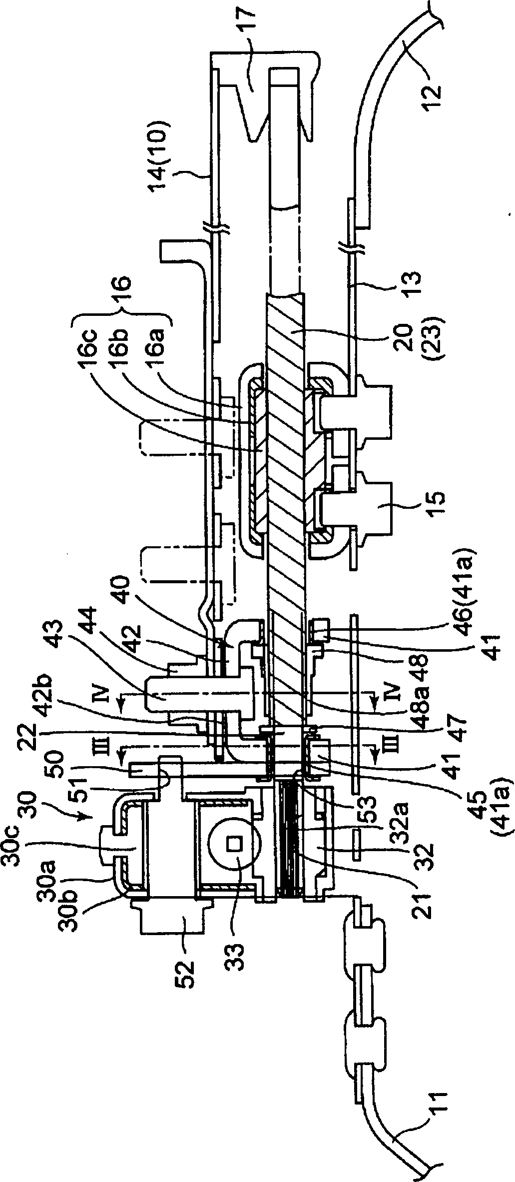
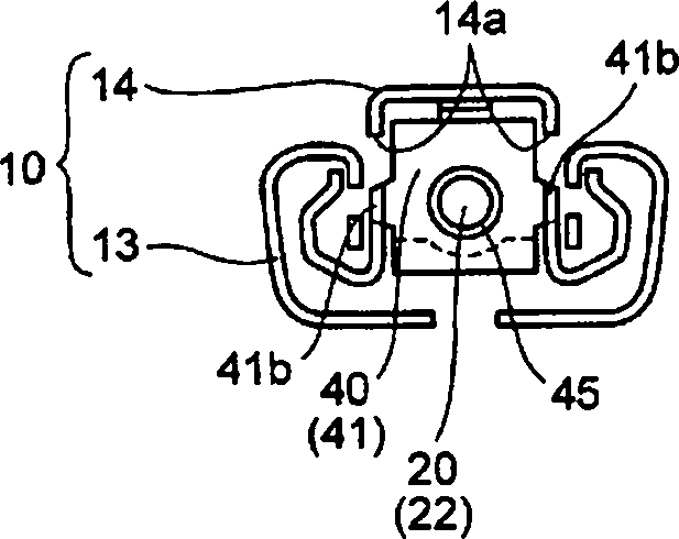
[0080] Such as Figure 13 As shown, the vehicle seat sliding device includes a pair of left and right seat adjustment slide rails 10 located between the vehicle seat S and the ground F and extending in the vehicle front and rear direction. The left and right seat adjustment slide rails 10 have the same (symmetrical) structure, and have a lower rail 13 fixed to the floor F through front and rear brackets 11 and 12, and an upper rail 14 fixed to the seat S, and the lower rail 13 and upper rail 14 are slidably fitted. The lower rail 13 and the upper rail 14 have openings facing each other.

[0081] Such as figure 1 As shown, the feed nut 16 facing the front-rear direction on the axis is fixed to the lower rail 13 by a fixing bolt 15. In the feed nut 16, a nut 16c made of synthetic resin is inserted into a metal casing 16a through a rubber sheet 16b for vibration absorption. The lower rail 13 is a feed nut fixing rail.

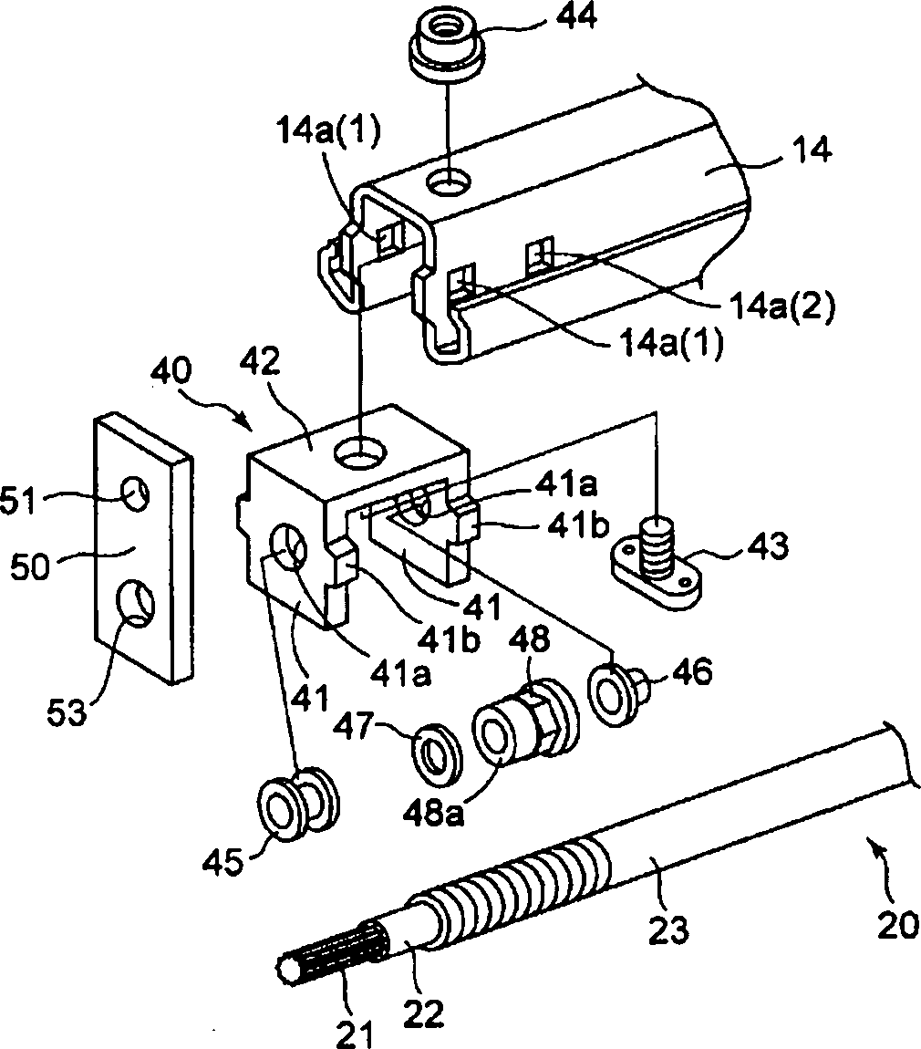
[0082] In contrast to this, the screw 20 screwed with the feed...


PUM


Abstract

The present invention provides a power slide device for a vehicle seat, configured such that an upper rail is moved in the front-rear direction by rotation and drive of a screw rod. A screw rod support rail is provided with a pair of load transmitting members separated in the front-rear direction, and the screw rod is provided with a load receiving member making contact with the pair of load transmitting members. When buckling occurs in the screw rod due to an axial force acting on the screw rod, the buckling is supported at multiple points, and this limits the direction of the buckling to reduce the amount of the buckling.

Description

Technical field [0001] The present invention relates to a power sliding device that moves a vehicle seat in the front-rear direction by an engine-driven feed screw mechanism. Background technique [0002] The seat sliding device for a vehicle has a basic structure in which an upper rail fixed to the seat and a lower rail facing the front-rear direction and fixed to the vehicle floor are slidably engaged with each other. This vehicle seat sliding device is freely supported on one of the upper rail and the lower rail by rotating a screw driven by the engine in the extending direction of the rail, and on the other hand, it is screwed to the screw nut of the screw The nut part is fixed to the other to realize motorization. [0003] The screw is rotatably supported between the gearbox and the bearing member, wherein the gearbox is provided at one end (generally the front end) of any one of the upper rail and the lower rail, and the bearing member is provided at the rear end. Furthermo...

Claims


Application Information

Patent Timeline
Patent Type & Authority Applications(China)
IPC IPC(8): B60N2/06F16H25/20F16H25/24
CPCB60N2/067B60N2/0705
Inventor 木村明弘青井宏仁伊藤敏治
Owner SHIROKI KOGYO CO LTD
Why Eureka
Try Eureka