Miter cutting machine

A technology of oblique cutting machine and frame, applied in shearing device, pipe shearing device, attachment device of shearing machine, etc., can solve the problems of unstable product size and low efficiency of manual operation.

Active Publication Date: 2013-04-03
ZHEJIANG AXILONE SHUNHUA ALUMINUM IND
View PDF12 Cites 9 Cited by
  • Summary
  • Abstract
  • Description
  • Claims
  • Application Information

AI Technical Summary

Problems solved by technology

[0008] The invention provides an oblique cutting machine, which can realize semi-automatic mass production and solve the problems of low manual operation efficiency and unstable product size in the prior art.

Method used


Image

  • Miter cutting machine
  • Miter cutting machine
  • Miter cutting machine

Examples


Embodiment Construction

[0079] The specific implementation manners of the present invention will be described in further detail below in conjunction with the accompanying drawings.

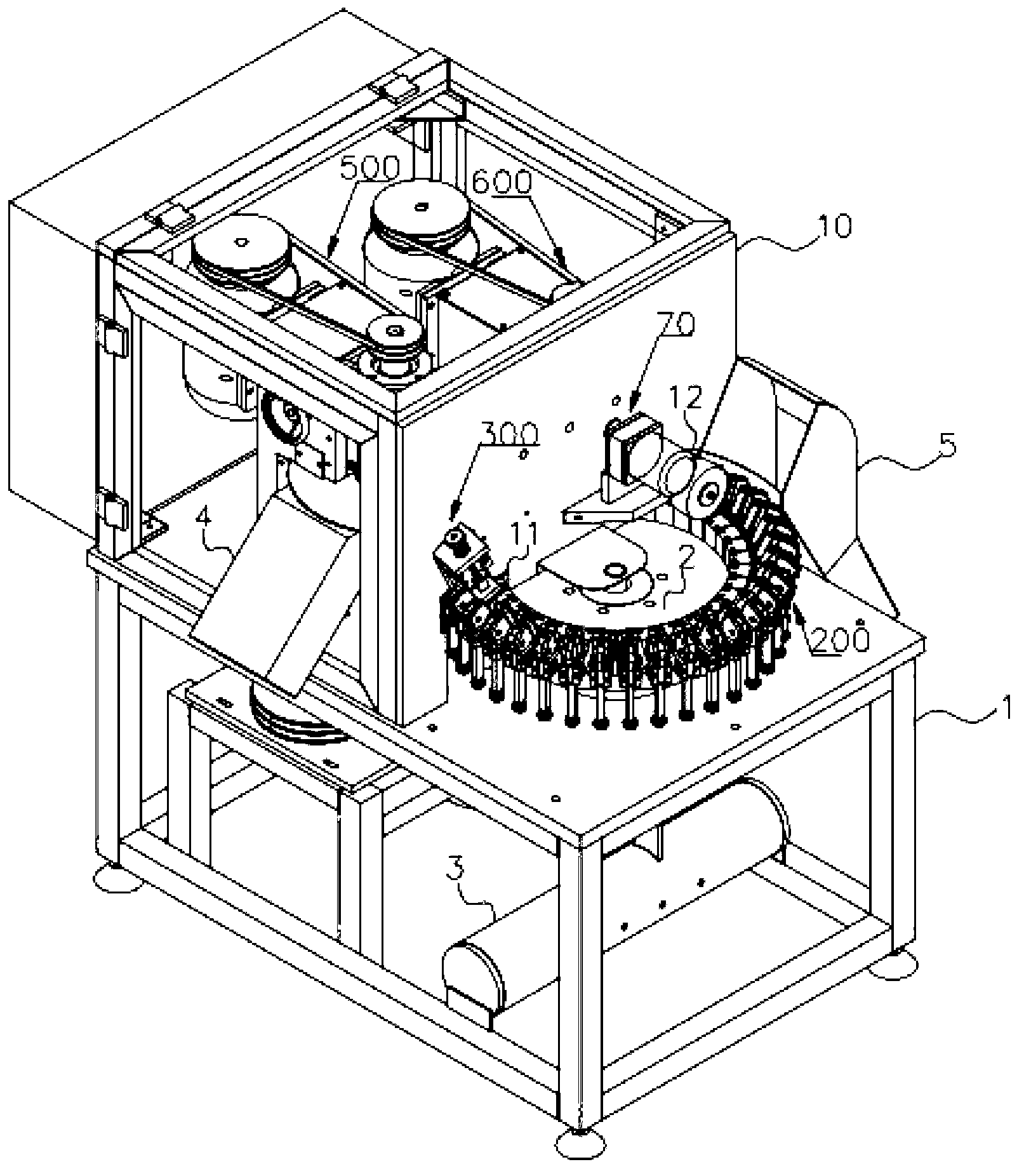
[0080] Such as figure 1 The bevel cutting machine shown includes: frame 1, horizontal turntable 2, compressed air source 3, protective box 10, jig 200, extrusion device 300, first rotary cutter 500, waste receiving groove 4, second rotary cutter 600, blanking device 70, workpiece receiving groove 5.

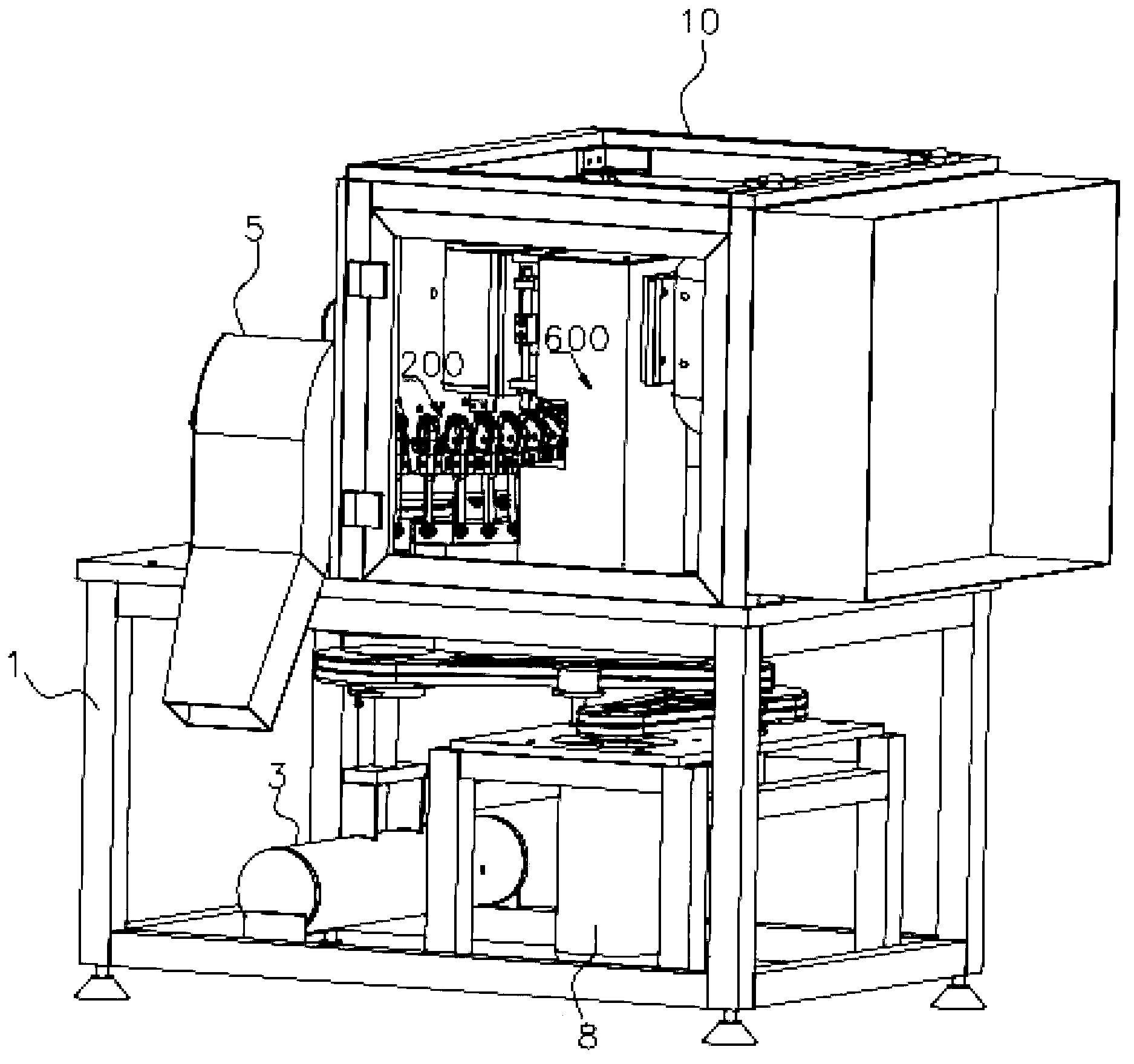
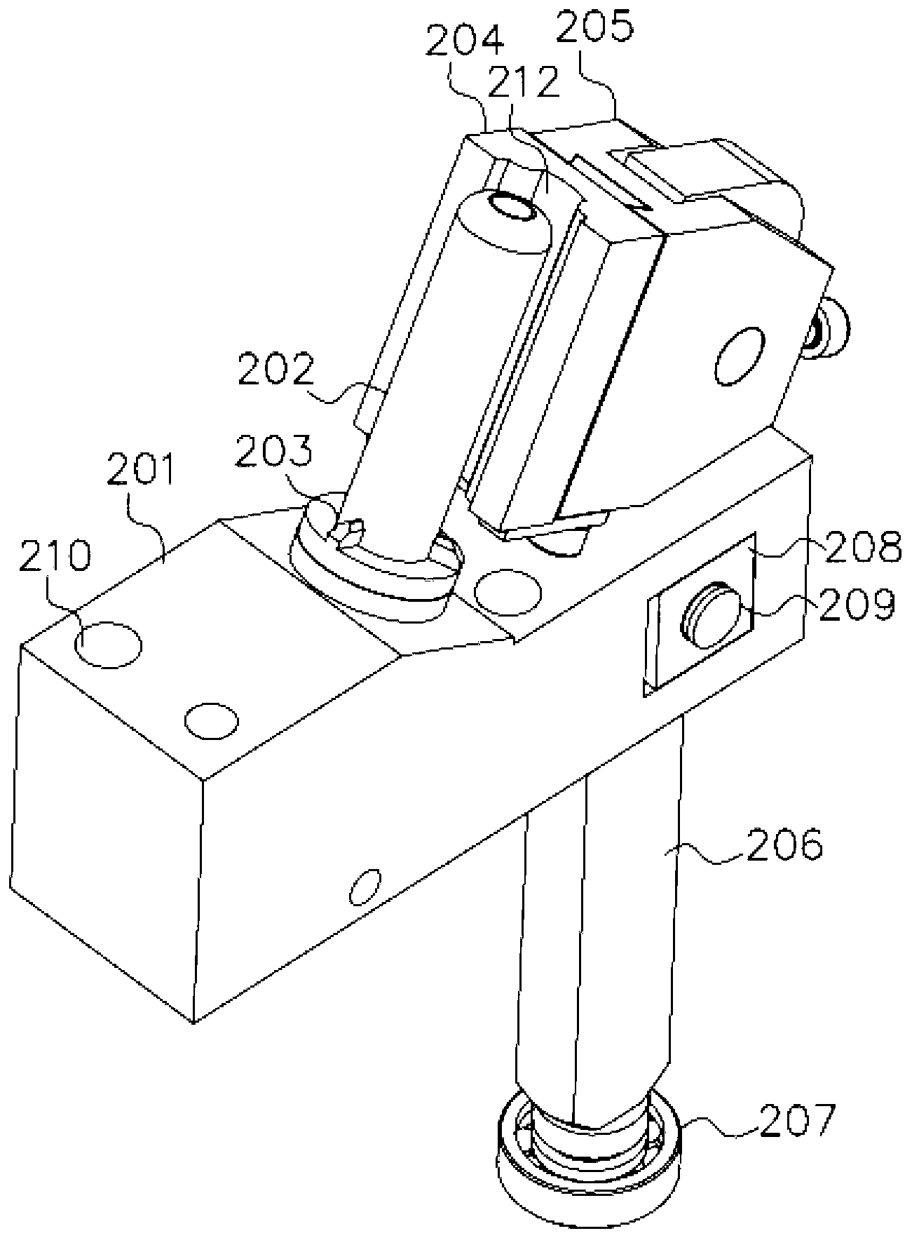
[0081] Depend on figure 1 and figure 2 It can be seen that the horizontal turntable 2 is installed on the frame 1, and the driving motor driving the rotation of the horizontal turntable 2 is installed under the frame 1. In this specific embodiment, a GV vertical three-phase gear reduction motor 8 is selected. On the edge of the horizontal turntable 2, a plurality of jigs 200 are installed along the circumference. The structure of each fixture 200 is as follows image 3 , 4 , 5, and 6.

[0082] combine figure 1 ,Dep...


PUM


Abstract

The invention discloses a miter cutting machine, which comprises a frame for fixing a workpiece and a cutting device for cutting the workpiece, wherein a horizontal rotating disc and a driving motor for driving the horizontal rotating disc are arranged on the frame; and a plurality of jigs are arranged on the edge of the horizontal rotating disc in the circumferential direction. Compared with the prior art, the miter cutting machine has the advantages as follows: the jigs are mounted on the horizontal rotating disc, so that a plurality of workpieces can be fed at a time, and continuous conveying and cutting are realized; the workpieces are pressed tightly by a downward pressing device, clamped by the jigs and a lug boss and automatically discharged by a discharging device, and operators only need to feed the workpieces, so that the degree of automatic production of the miter cutting machine is increased, and the production efficiency is improved; the miter cutting machine can be adjusted in height, thereby meeting the requirements of products with different sizes; the miter cutting machine can perform precise cutting, so that the cut of an obtained product is smooth in cut and no burr exists at the periphery of the cut; and the miter cutting machine is convenient for size adjustment of the product.

Description

technical field [0001] The invention relates to a bevel cutting machine for metal processing, in particular to a bevel cutting machine capable of continuous cutting. Background technique [0002] The middle beam core is the main part of the lipstick packaging tube. It is mainly composed of the middle beam, the middle section, the beads and the spiral. Generally, the middle beam and the middle section are fixedly connected, the spiral and the middle section are axially fixed, and the beads and the middle section are radially fixed. , during the rotation of the helix relative to the middle section, the helix relies on the helical groove on the inner wall to drive the beads to reciprocate in the middle bundle. [0003] The Chinese utility model patent with the publication number of 201509802U discloses a middle beam core of a lipstick tube, including a middle beam, a bead and a helix. There is a protrusion, the middle beam is provided with an axial groove matching the protrusi...

Claims


Application Information

Patent Timeline
Patent Type & Authority Applications(China)
IPC IPC(8): B23D21/02B23D33/00B23D33/02
Inventor 卢建锋
Owner ZHEJIANG AXILONE SHUNHUA ALUMINUM IND
Why Eureka
Try Eureka