Balance valve with quickly-closing valve plug

A technology of balance valve and valve core, applied in the field of balance valve, can solve the problems of prolonged valve core closing time, dangerous smooth operation of the whole machine, large sinking distance of heavy objects, etc., to achieve strong design reliability, perfect design function, and use long life effect

Active Publication Date: 2012-11-28
YUZHOU HYDRAULIC EQUIP FACTORY
View PDF1 Cites 2 Cited by
  • Summary
  • Abstract
  • Description
  • Claims
  • Application Information

AI Technical Summary

Problems solved by technology

The existing balance valve hydraulic components have reached a certain level of valve sealing and self-locking functions, and have high requirements for the stability of the balance valve, so the valve basically has a structure that can move the valve core smoothly, but this It also caused the lengthening of the closing time of the spool, resulting in the excessive sinking distance of the weight when the valve stem returns to the neutral position in the hydraulic system. Now this distance error is usually compensated by the operator's work skills, giving The operation increases the difficulty and also causes the instability in the work
However, if the valve core closes too quickly, it will cause instantaneous high pressure in the rodless chamber of the cylinder, resulting in a certain force impact, which will bring certain danger to the smooth operation of the whole machine.

Method used


Image

  • Balance valve with quickly-closing valve plug
  • Balance valve with quickly-closing valve plug
  • Balance valve with quickly-closing valve plug

Examples


Embodiment Construction

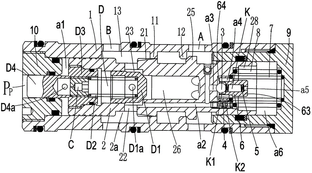
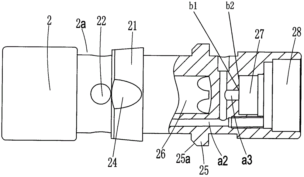
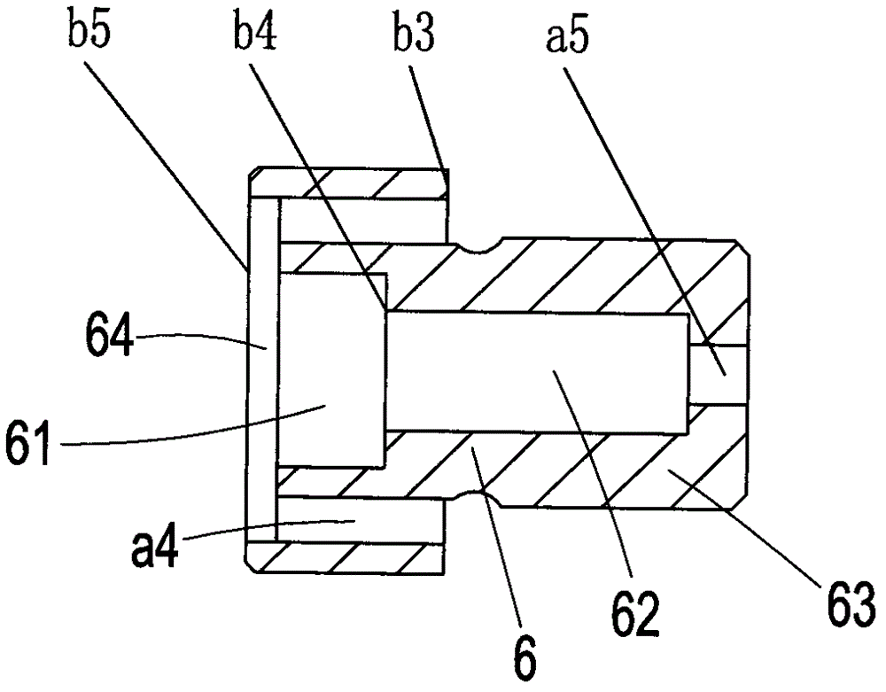
[0027] The present invention will be further described in detail below in conjunction with the accompanying drawings and embodiments.

[0028] Such as Figure 1 to Figure 4 As shown, the icon numbers are explained as follows: valve sleeve 1, front stop ring 11, rear stop ring 12, through hole 13, main valve core 2, inner concave ring body 2a, front cut-off body 21, perforation 22, front one-way Valve hole 23, throttle groove 24, rear stop body 25, inclined surface 25a, intermediate transition hole 26, spring cover hole 27, rear concave hole 28, steel ball 3, damping 4, steel ball spring 5, spring cover 6, steel ball hole 61, spring hole 62, pin-shaped body 63, ring hole 64, small coil diameter spring 7, large coil diameter spring 8, rear end cover 9, front end cover 10, first main oil port A, first working oil port A1, Second main oil port B, second working oil port B1, fourth working oil port B2, third working oil port B3, leakage damping C, main check valve assembly D, plug...


PUM


Abstract

The invention discloses a balance valve with a quickly-closing valve plug. The front side and the rear side of a valve bush shell surface are respectively provided with a first main oil port and a second main oil port; the middle of a valve bush is provided with a through hole in sliding fit with the main valve plug; two ends of the through hole are respectively sealed and assembled with a front end cover and a rear end cover; the front end and the rear end of the middle of a main valve plug are respectively assembled with a main check valve assembly and a quickly-closing check valve assembly; the quickly-closing check valve assembly comprises a check valve and a throttle valve which are arranged in parallel, wherein a free flowing-in end of the check valve is communicated with the secondmain oil port; the front end cover is provided with an outer control port which controls the main valve plug to slide and operate backwards; the valve bush, the main valve plug, each check valve, thethrottle valve and the like which are in an internal and external matching and sliding structure are adopted, integral design is reasonable, and structure is compact; the check valve structure is simultaneously embedded in a rear cavity of the main valve plug, so that sinking distance when a hydraulic cylinder retracts during practical operation can be effectively reduced, and the structure is simple; and when the valve is operated to open, the stability of integral operation is guaranteed when the main valve plug automatically resets, and thus the balance valve has the advantages of reliabledesign and long service life.

Description

technical field [0001] The invention relates to the technical field of vehicle-mounted hydraulic valves, in particular to a balance valve with a quick-closing valve core. Background technique [0002] In modern construction machinery, construction machinery and other engineering equipment, the hydraulic load-bearing system has become the main application object, and the balance valve is the key hydraulic component of this type of system, and its performance directly affects the performance of the whole machine. With the development of the national economy and the increasing requirements and difficulties of the operation of the hydraulic machinery industry, customers have reached a new height in the performance and functional diversity of the balance valve. The existing balance valve hydraulic components have reached a certain level of valve sealing and self-locking functions, and have high requirements for the stability of the balance valve, so the valve basically has a stru...

Claims


Application Information

Patent Timeline
Patent Type & Authority Patents(China)
IPC IPC(8): F15B13/02
Inventor 卢宇邹泉敏王河君
Owner YUZHOU HYDRAULIC EQUIP FACTORY
Why Eureka
Try Eureka