Eureka AIR delivers breakthrough ideas for toughest innovation challenges, trusted by R&D personnel around the world.

Electric connector assembly

An electrical connector and connector technology, applied in the direction of conductive connection, electrical component connection, connection, etc., can solve the problems of USB connector separation and easy wear and tear

Inactive Publication Date: 2011-05-25
INVENTEC CORP
View PDF0 Cites 5 Cited by
  • Summary
  • Abstract
  • Description
  • Claims
  • Application Information

AI Technical Summary

Problems solved by technology

[0006] In view of the above problems, the technical problem to be solved by the present invention is to provide an electrical connector assembly to solve the problem in the prior art that the terminals of the USB connector are easy to wear when plugging in and out, and at the same time avoid unintended external force pulling and damage. Causes problems such as separation of two USB connectors

Method used


Image

  • Electric connector assembly
  • Electric connector assembly
  • Electric connector assembly

Examples


Embodiment Construction

[0040] The electrical connector assembly disclosed in the present invention can be applied to but not limited to electronic devices having electrical connector assemblies such as notebook computers, mobile phones, personal digital assistants (PDAs), portable navigation devices, printers, and transformers. Furthermore, the electrical connector assembly according to the present invention can also be applied but not limited to the electrical connection between peripheral devices and computer devices. In other words, the electrical connector assembly according to the present invention can be applied to the electrical connection between electronic devices and transmission wires.

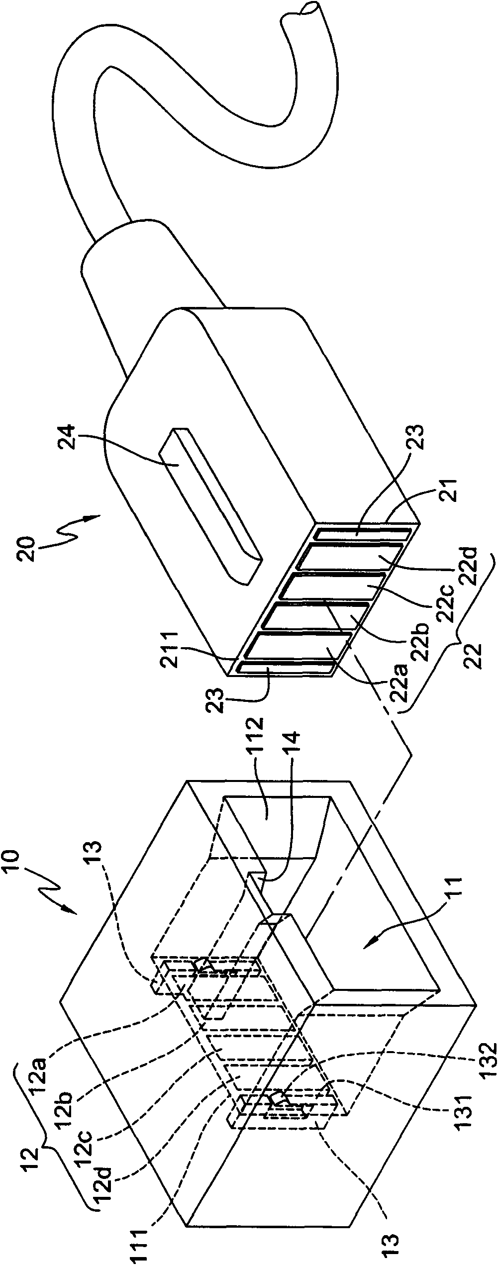
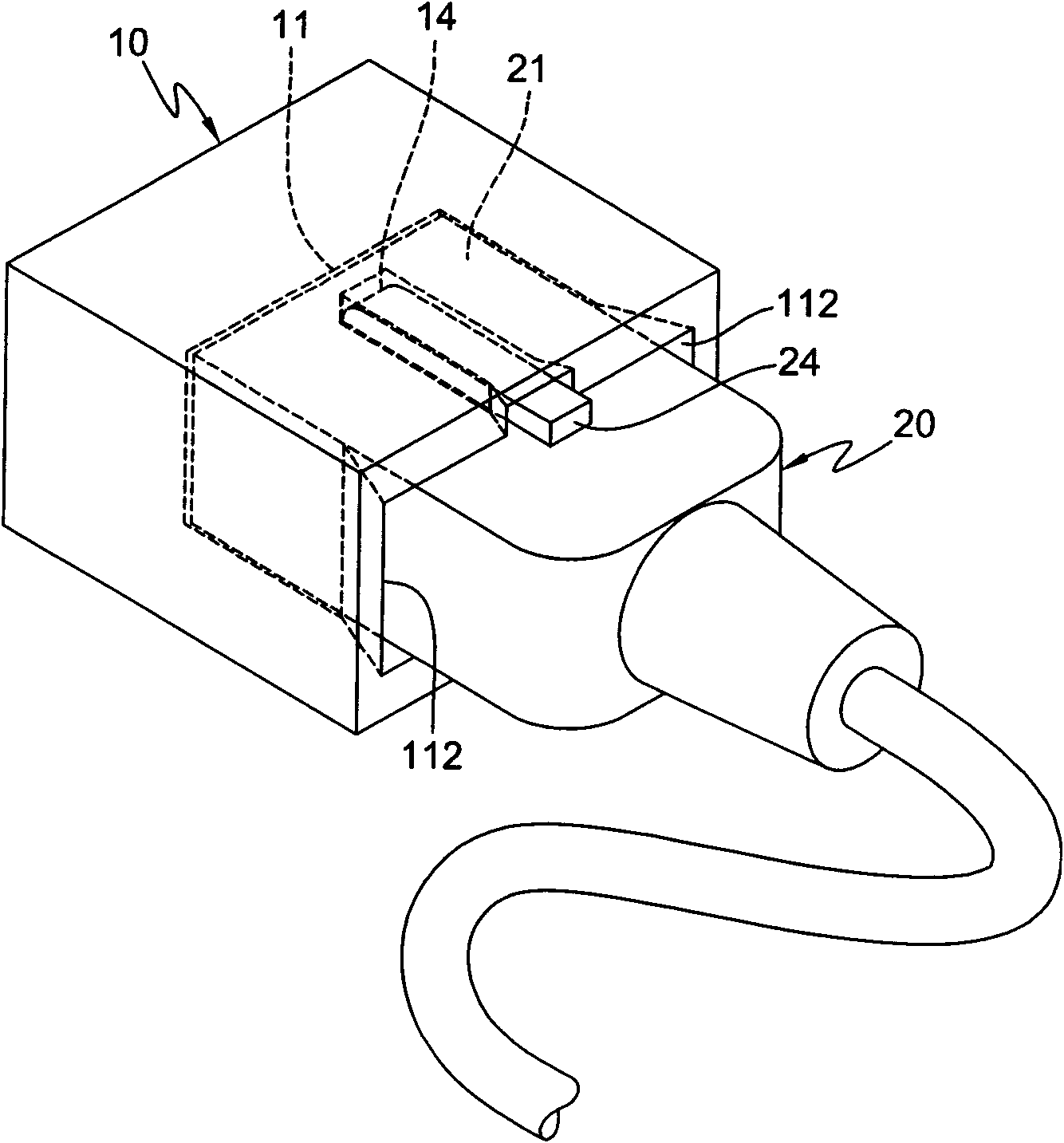
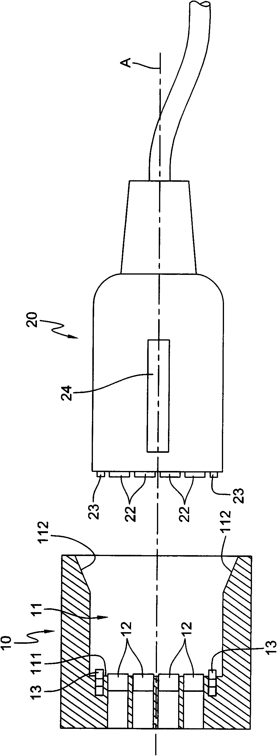
[0041] Please also see Figure 1 to Figure 4 shown. in, figure 1 It is an exploded schematic view of the electrical connector assembly of the present invention. figure 2 It is a schematic diagram of the assembly of the electrical connector assembly of the present invention. image 3 It is a schematic...


PUM


Abstract

The invention relates to an electric connector assembly. The electric connector assembly comprises a first connector and a second connector, wherein the first connector is provided with a slot in which a plurality of first electric connecting pieces and at least one metal member are arranged; one end of the metal member is provided with an elastic sheet and a cambered bump; the cambered bump is arranged on the elastic sheet and is normally kept in the slot; the second connector is connected to the first connector along an assembly direction and is provided with a butting end part; the butting end part is provided with a setting surface perpendicular to the assembly direction; the setting surface is provided with a plurality of second electric connecting pieces and at least one magnetic member; the butting end part is correspondingly assembled in the slot; and the magnetic member of the butting end part is pressed against the elastic sheet of the metal member, so the magnetic member adsorbs the cambered bump of the metal member, and the second electric connecting piece is mutually contacted with the first electric connecting piece.

Description

technical field [0001] The invention relates to an electrical connector assembly, in particular to an electrical connector assembly guided and assembled by magnetic force. Background technique [0002] With the rapid development of the electronic technology industry, various high-tech electronic devices are constantly being developed and produced on the market. In order to make the functions of electronic devices more abundant and practical, various auxiliary devices and accessories derived from electronic devices are also continuously developed. It was invented to make people have better efficiency in the application of various electronic devices. [0003] The electrical connection between two electronic devices is usually through two corresponding electrical connectors, so as to provide signal transmission between the two devices. For example, peripheral devices such as external hard disks, personal digital assistants (Personal Digital Assistant; PDA), portable navigation...

Claims


Application Information

Patent Timeline
Patent Type & Authority Applications(China)
IPC IPC(8): H01R24/00H01R13/639H01R13/629H01R11/30
Inventor 张丛才
Owner INVENTEC CORP
Why Eureka
Eureka Blog
Learn More