Transmission resource allocation method and equipment

A technology of transmission resources and allocation methods, applied in the field of transmission resource allocation methods and equipment, to achieve the effect of saving costs and reducing demand

Active Publication Date: 2011-05-25
DATANG MOBILE COMM EQUIP CO LTD
View PDF3 Cites 13 Cited by
  • Summary
  • Abstract
  • Description
  • Claims
  • Application Information

AI Technical Summary

Problems solved by technology

[0006] The technical problem solved by the present invention is to provide a method and equipment for allocating transmission resources, which are used to

Method used


Image

  • Transmission resource allocation method and equipment
  • Transmission resource allocation method and equipment
  • Transmission resource allocation method and equipment

Examples


Embodiment 1

[0085] Take F(1) traffic as an example:

[0086](1) For an eNodeB that supports 3 cells, the uplink resource allocated by operation and maintenance at the S1 interface is V_F(1)=60Mbps due to the limited bandwidth, converted to V_Bytes_F(1)=60M*100ms / 8=750KBytes;

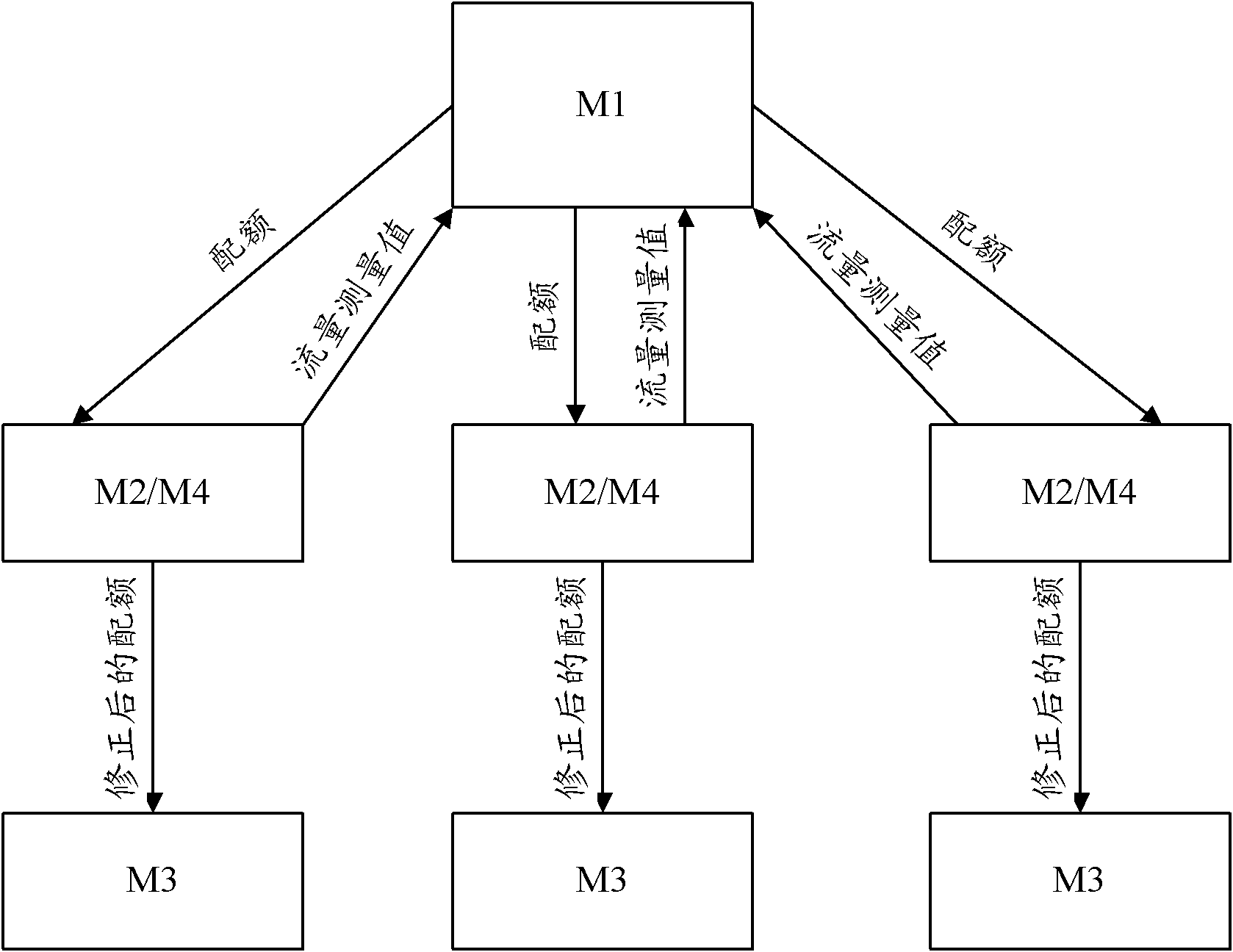
[0087] (2) QuotaF(1)[i]=750 / 3=250KBytes of each community at the beginning of M1, i takes a value of 1..3; M1 configures QuotaF(1)[i] to the M2 module of each community;

[0088] (3) After a period of 100ms, M2 reports to M1 that the actual sent data volumes of the three cells are 252Kbytes, 250Kbytes, and 150KBytes respectively; if deltaMin=5Kbytes, then A(k)={1, 2}; D(k)={ 3};

[0089] deltaF(1)[1]=252-250=2KBytes; this 2KBytes is caused by inaccurate estimation of headers by bandwidth usage modules such as MAC;

[0090] deltaF(1)[2]=deltaF(1)[3]=0;

[0091] Since 252+250+150<750, b=0;

[0092] (4) sumD(k)=250Kbytes-150Kbytes=100Kbytes, then

[0093] QuotaF(1)[1]=QuotaF(1)[2]=250+100 / 2=300KBytes;

[0094] Quo...

Embodiment 2

[0103] Take F(2) traffic as an example:

[0104] (1) For an eNodeB that supports 3 cells, the uplink resource allocated by operation and maintenance at the S1 interface due to bandwidth limitation is V_F(2)=6Mbps, converted to V_Bytes_F(2)=6M*100ms / 8=75KBytes;

[0105] (2) QuotaF(2)[i]=75 / 3=25KBytes of each community in M1 initial stage, i takes a value of 1..3; M1 configures QuotaF(1)[i] to the M2 module of each community;

[0106] (3) After a period of 100ms, M2 reports to M1 that the actual data volumes sent by the three cells are 26Kbytes, 28Kbytes, and 24KBytes respectively; if deltaMin=500Bytes, then A(k)={1, 2}; D(k)={ 3};

[0107] deltaF(2)[1]=26-25=1KBytes; deltaF(2)[2]=28-25=3KBytes; deltaF(2)[3]=0;

[0108] Since 26+28+24>75KBytes, b=1;

[0109] (4) M1 calculation: sumD(k)=25Kbytes-24Kbytes=1Kbytes, then

[0110] QuotaF(2)[1]=QuotaF(2)[2]=25+1 / 2=25.5KBytes;

[0111] QuotaF(2)[3]=24KBytes;

[0112] (5) M2 notifies M3 to set variable LeftScheBytesF(2)[i]=QuotaF(2...


PUM


Abstract

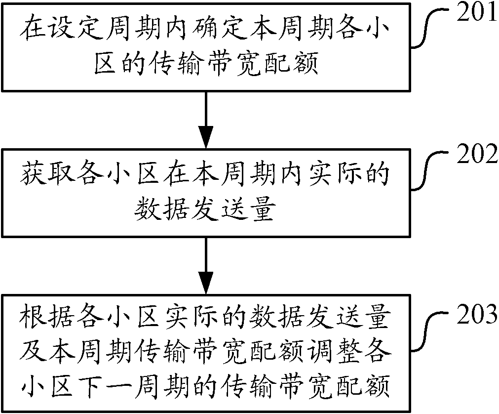
The invention discloses a transmission resource allocation method and transmission resource allocation equipment. The method comprises the following steps of: determining the transmission bandwidth quota of every cell in a set period; acquiring the actual data transmitting quantity of every cell in the period; and adjusting the transmission bandwidth quota of every cell in a next period accordingto the actual data transmitting quantity and the transmission bandwidth quota of every cell in the period. The requirement on the transmission bandwidth in a long-term evolution system can be reduced, and the transmission bandwidth can be shared among the cells of the same base station, so that the cost of operators can be effectively saved.

Description

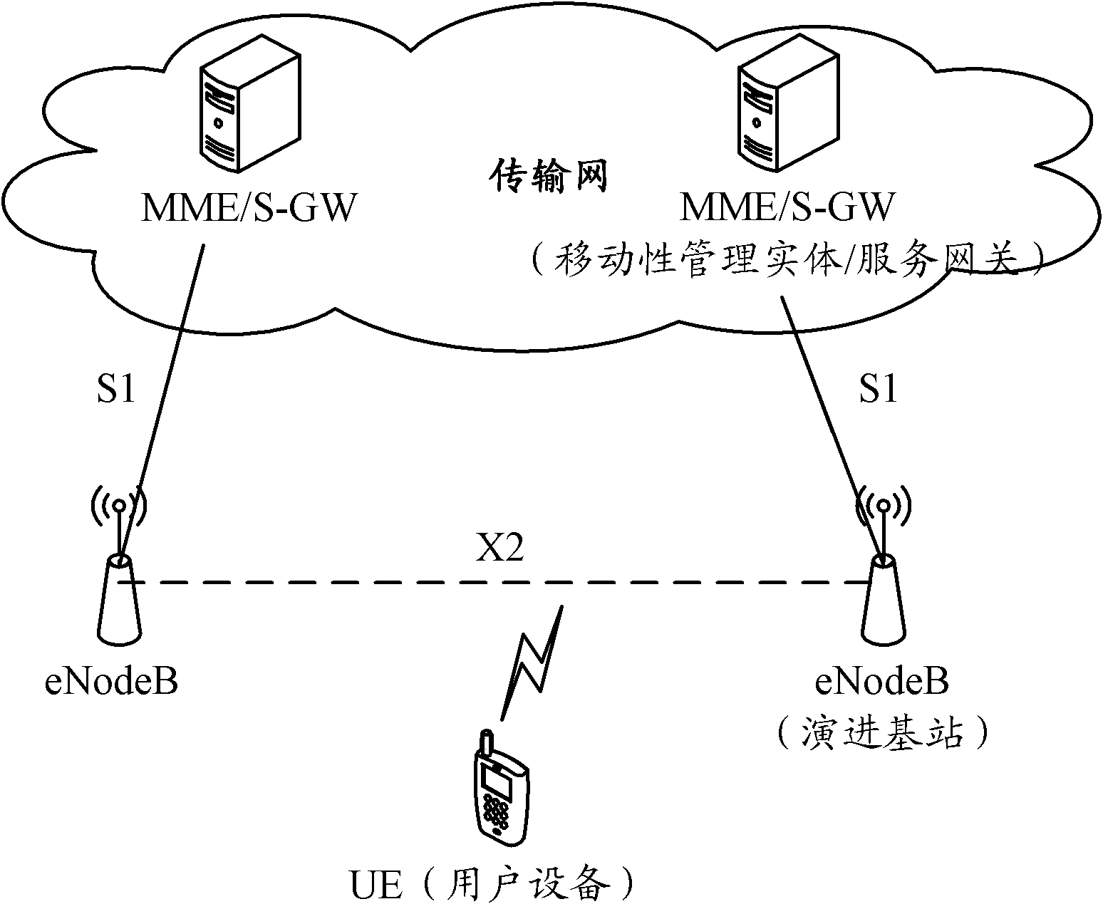
technical field [0001] The present invention relates to wireless communication technology, in particular to a transmission resource allocation method and equipment. Background technique [0002] figure 1 It is a schematic diagram of the overall architecture of the LTE (Long Term Evolution, long-term evolution) network. As shown in the figure, in the overall network architecture of the LTE system, the S1 port represents the eNodeB (evolved base station) and the MME (Mobility Management Entity, mobility management entity) / For an interface between S-GWs (Serving Gateway, serving gateway), the X2 port represents an interface between an eNodeB and a neighboring eNodeB. The UE (User Equipment, user equipment) communicates with the eNodeB through an air interface, and the S1 or X2 interface communicates through a transmission network. [0003] There are multiple cells in the eNodeB device, such as 3 cells, and the throughput of each cell in the uplink direction of the S1 port (t...

Claims


Application Information

Patent Timeline
IPC IPC(8): H04W28/10H04W28/20
Inventor 李远军李裕国阮楠蒋一鸣孙军帅李红雨
Owner DATANG MOBILE COMM EQUIP CO LTD
Why Eureka
Try Eureka