
Inspection apparatus for appearance of workpiece and inspection method thereof

A technology for visual inspection devices and workpieces, which is applied to conveyor objects, transportation and packaging, etc., can solve the problems of decreased camera accuracy, decreased electrostatic adsorption force, influence, etc., and achieves the effect of improving camera accuracy and processing capacity.

Active Publication Date: 2011-06-01
TOKYO WELD CO LTD
View PDF3 Cites 16 Cited by
  • Summary
  • Abstract
  • Description
  • Claims
  • Application Information

AI Technical Summary

Problems solved by technology

However, when transferring workpieces from the linear feeder to the transfer table, the workpieces may not always be transferred in a fixed direction. Since the posture of the workpiece after transfer is fixed by electrostatic attraction, the Subtle differences occur in the posture of each workpiece, which may reduce the imaging accuracy
[0008] In addition, the workpiece is charged while being conveyed in the linear feeder, so the workpiece is attracted to the linear feeder by virtue of electrostatic adsorption during conveyance, which may cause a decrease in conveying speed, and in the worst case cause the workpiece to stop
[0009] The second problem is to reduce the electrostatic adsorption force after the workpiece is transferred
Therefore, part of the charge of the workpiece immediately before being transferred to the transfer table is canceled, and in this case, the electrostatic attraction force acting on the workpiece placed on the transfer table is reduced.
[0011] The third problem is the impact of static electricity on the workpiece
When the workpiece placement surface is brought into contact with the workpiece by the above-mentioned workpiece transfer, there is a risk of electrostatic breakdown of the workpiece or deterioration of characteristics due to charge cancellation due to the movement of the accompanying charges.

Method used


Image

  • Inspection apparatus for appearance of workpiece and inspection method thereof
  • Inspection apparatus for appearance of workpiece and inspection method thereof
  • Inspection apparatus for appearance of workpiece and inspection method thereof

Examples


no. 1 approach

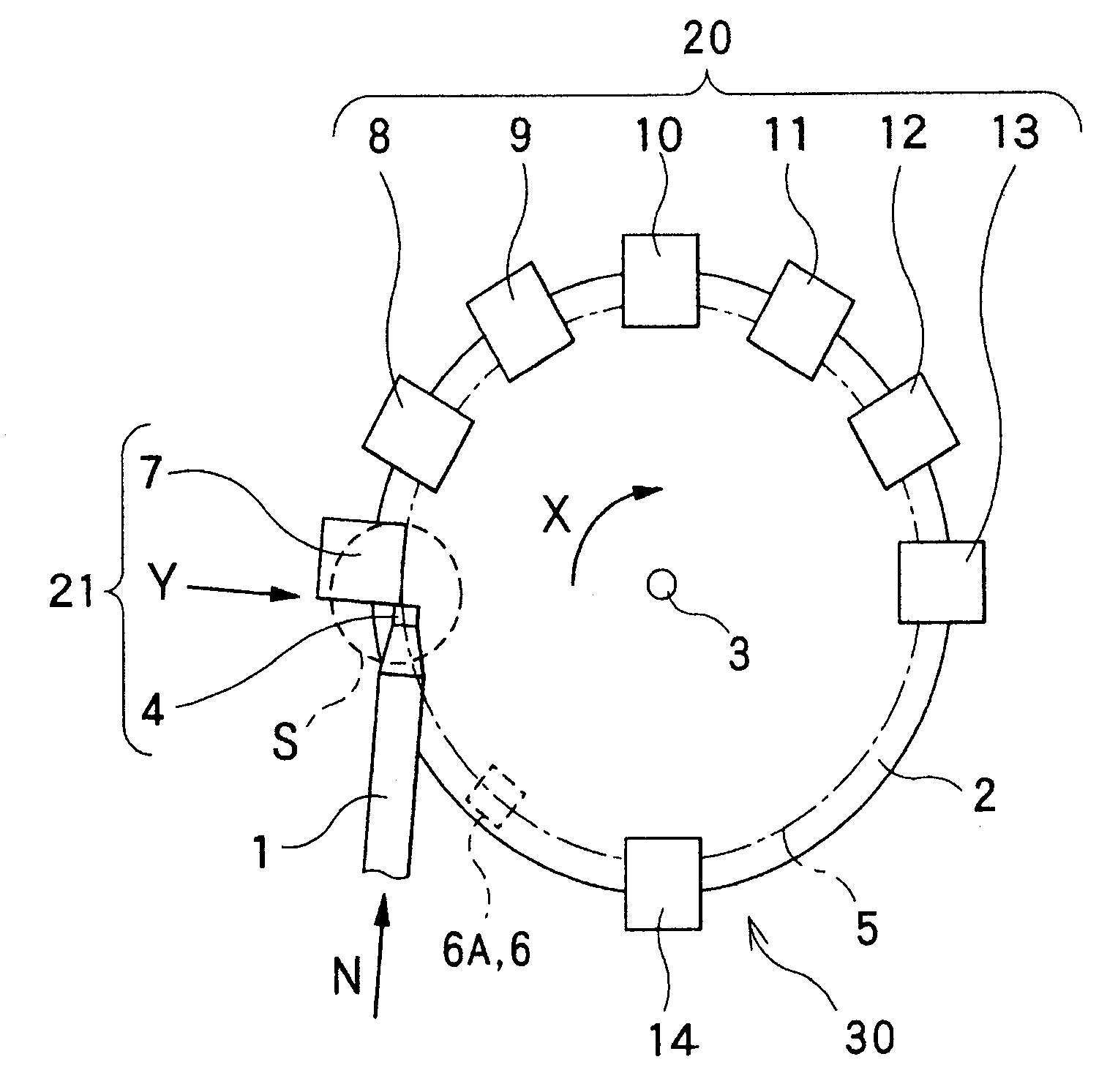
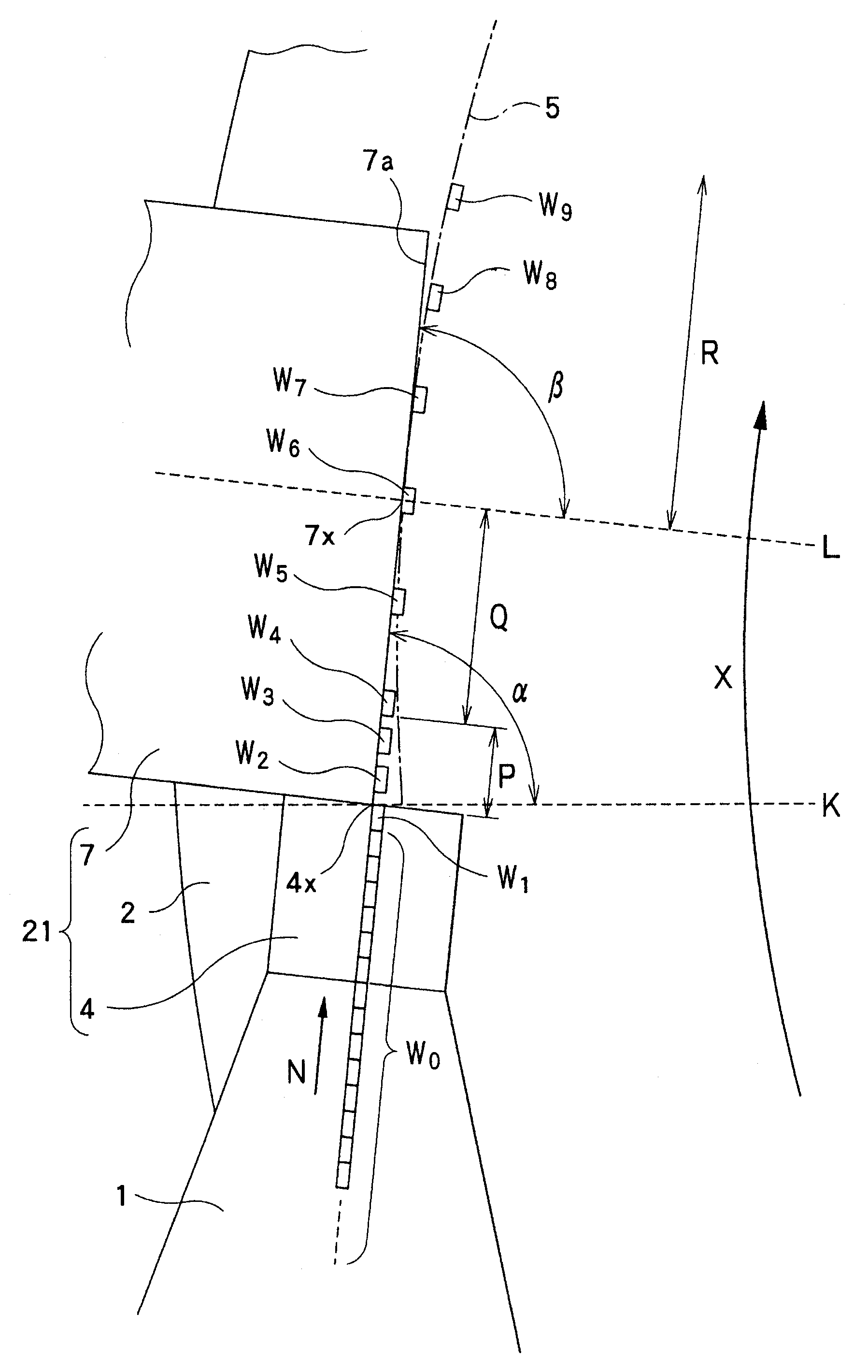
[0063] Hereinafter, embodiments of the present invention will be described with reference to the drawings. Figure 1 to Figure 9 It is a figure which shows the 1st Embodiment of the appearance inspection apparatus of the workpiece|work of this invention, and the appearance inspection method of a workpiece.

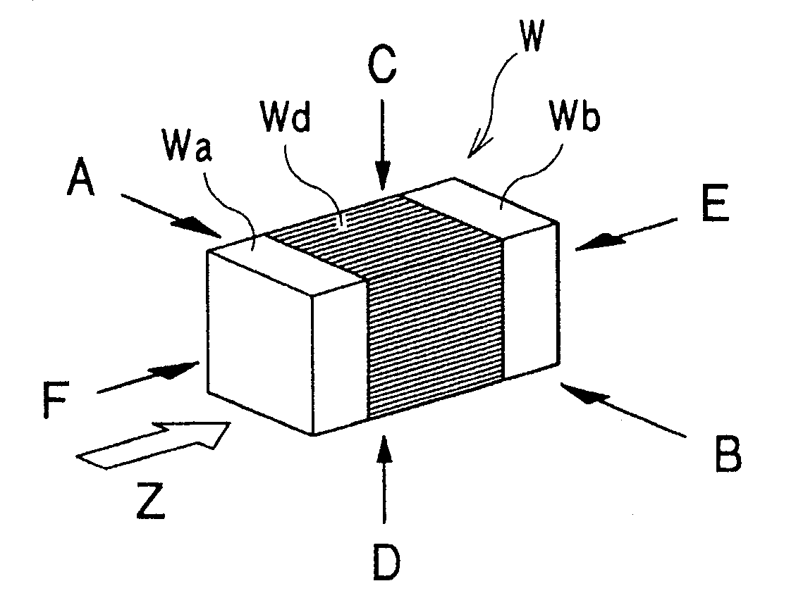
[0064] First, use figure 2 , the workpiece inspected by the workpiece appearance inspection device will be described.

[0065] exist figure 2 Among them, the workpiece W composed of chip components such as capacitors and resistors has a hexahedron shape, has a main body Wd made of an insulator, and electrodes Wa and Wb made of conductors formed at both ends in the longitudinal direction of the main body Wd. In the case of visually inspecting the workpiece W, the workpiece W is placed on the transfer table 2 described later, and the transfer table 2 is figure 2 Rotate in the direction of the arrow Z to transport the workpiece W. Then, the side surface on the opposite...

no. 2 approach

[0115] Next, use Figure 10 to Figure 15 , the second embodiment of the present invention will be described.

[0116] Figure 10 to Figure 15 The shown second embodiment of the present invention differs from the first embodiment only in that a conductive plate (conductor) 15 is arranged below the transfer table 2 instead of arranging the charging unit 6A below the transfer table 2 , other structures with Figure 1 to Figure 9 The first embodiment shown is substantially the same.

[0117] exist Figure 10 to Figure 15 The second embodiment shown, with Figure 1 to Figure 9 The parts that are the same as those in the first embodiment shown are given the same symbols, and detailed descriptions will be omitted.

[0118] here, Figure 10 is viewed from the direction of the arrow Y figure 1 The perspective view seen in the region S enclosed by the dashed line in , corresponding to Figure 4 . exist Figure 10 Among them, on the lower side of the transfer table 2, a conduct...


PUM


Abstract

The invention provides an inspection apparatus for the appearance of a workpiece and an inspection method thereof,wherein workpieces can be correctly positioned on a conveyance workbench and the electrostatic destruction or the characteristic deterioration of the workpieces are avoided.The inspection apparatus (30) for the appearance of workpieces comprises a linear feeder (1) for transferring hexahedron-shaped workpieces (W),a conveyance workbench (2), a transferring arrangement unit (21), an electrifying unit (6A) and an imaging unit(20).The conveyance workbench (2) transfers and transportsthe workpieces (W) obtained from the linear feeder (1).The workpieces (W) obtained from the linear feeder (1) are then transferred and arranged on the conveyance workbench (2) by the transferring arrangement unit (21).The lower surface of the conveyance workbench (2) is electrified and the workpieces are held by the electrifying unit (6A).The six surfaces of the workpieces (W) are recorded by theimaging unit (20).The transferring arrangement unit (21) comprises a vibration-free part (4) arranged between the linear feeder (1) and the conveyance workbench (2) and an arrangement guiding part (7).The workpieces are arranged in a W shape by the arrangement guiding part (7).When viewed from a plane, the arrangement guiding part (7) is equipped with a linear guiding face (7a).

Description

technical field [0001] The present invention relates to a workpiece appearance inspection device and a workpiece appearance inspection method that image a hexahedron of the workpiece while conveying the hexahedron workpiece. Background technique [0002] Conventionally, as an appearance inspection device for a chip-shaped electronic component such as a hexahedral resistor or capacitor (hereinafter referred to as a "workpiece"), there is known a device in which the workpiece is placed on a transparent body made of glass or the like. On the transfer table, while the transfer table is rotated to transfer the workpiece, an image pickup unit such as a camera takes pictures of each surface for visual inspection. [0003] In this case, the workpiece conveying table of the visual inspection device uses static electricity to electrostatically attract and convey the workpiece. [0004] That is, first, the workpiece is charged on the linear feeder (Linear Feeder) that aligns and conve...

Claims


Application Information

Patent Timeline
Patent Type & Authority Applications(China)
IPC IPC(8): B65G47/80
Inventor 小寺克义望月弘之后藤翼
Owner TOKYO WELD CO LTD
Learn More