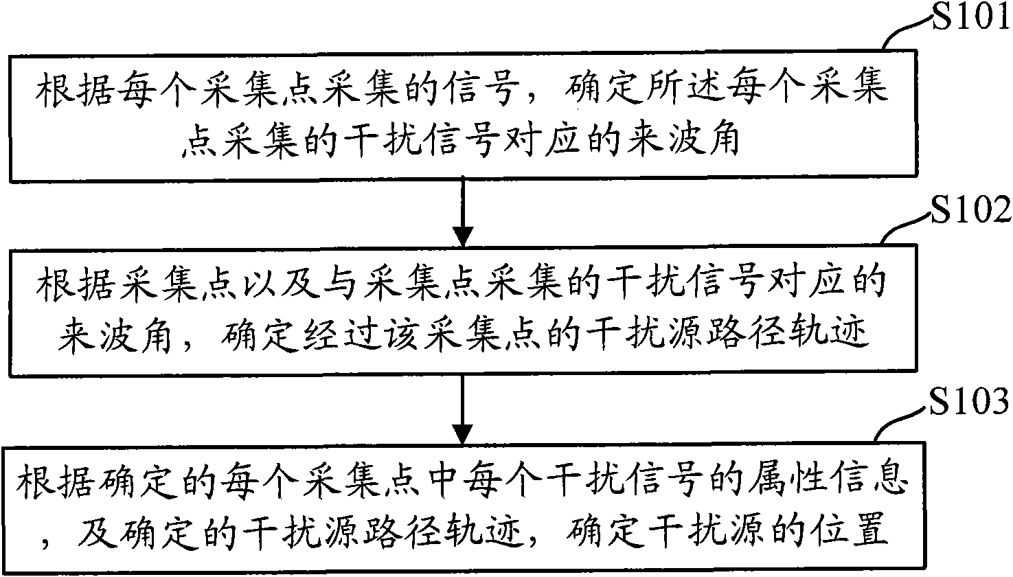
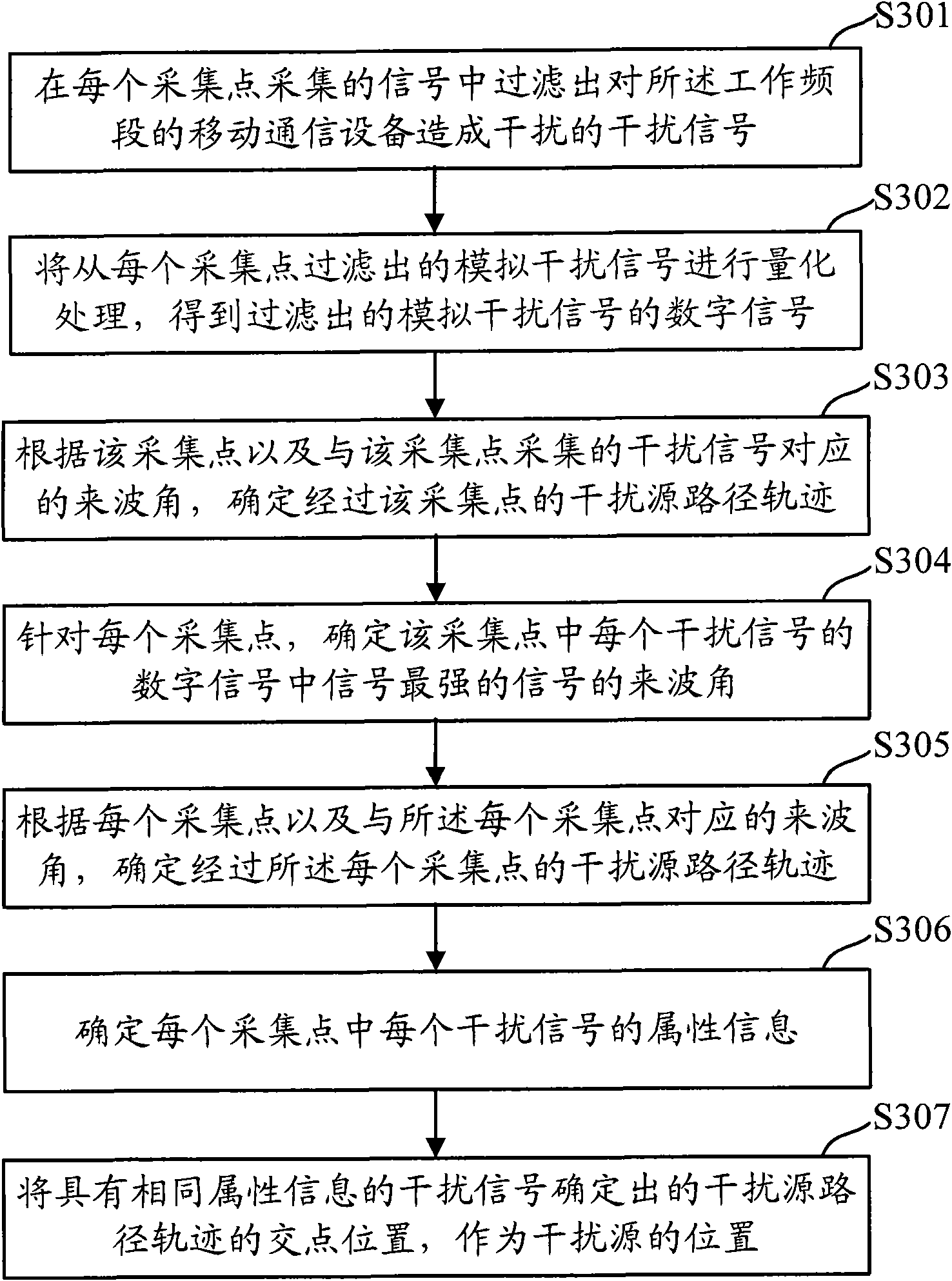
[0021] In order to effectively improve the accuracy of interference source positioning, the embodiment of the present invention provides a method for interference source positioning. The interference source positioning method includes: determining the arrival angle corresponding to the interference signal collected at each collection point, and determining the path The interference source path trajectory of the collection point is determined, the attribute information of each interference signal in each collection point is determined, and the attribute information of each interference signal in each collection point is determined, and the determined interference source path trajectory , To determine the location of the interference source. Since the interference signal with the same attribute information may be the interference signal from the same interference source, in the embodiment of the present invention, the intersection of the path trajectory determined by the arrival angle corresponding to the interference signal with the same attribute information is used as the position of the interference source , Thereby effectively eliminating the interference caused by the refraction of the building to the signal and the interference caused by the superposition of different interference source signals, so that the determined interference source location is more accurate.
[0022] The embodiments of the present invention will be described in detail below with reference to the drawings in the specification.
[0023] figure 1 This is a process of locating an interference source provided by an embodiment of the present invention, and the process includes the following steps:
[0024] S101: Determine the arrival angle corresponding to the interference signal collected by each collection point according to the signal collected by each collection point.
[0025] When determining the arrival angle corresponding to the interference signal collected by each collection point, according to the current working frequency band of the mobile communication device, filter out the interference signal that causes interference to the interference frequency band from the signals collected by each collection point, and The interference signal filtered from each collection point is subjected to quantization processing, and the arrival angle corresponding to the interference signal collected at each collection point is determined according to each interference signal after the quantization processing.
[0026] S102: For each collection point, determine the interference source path trajectory passing through the collection point according to the collection point and the arrival angle corresponding to the interference signal collected by the collection point;
[0027] Wherein determining the path trajectory of the interference source passing through the collection point includes: taking the collection point as the end point of the ray, and the angle of arrival corresponding to the interference signal corresponding to the collection point as the included angle, and determining the interference source path passing through the collection point Track.
[0028] S103: Determine the attribute information of each interference signal in each collection point, and determine the location of the interference source according to the determined attribute information of each interference signal in each collection point and the determined path trajectory of the interference source .
[0029] The attribute information of each interference signal includes time domain information, frequency domain information, or amplifier distortion information of each interference signal.
[0030] The determining the location of the interference source specifically includes: counting the time domain information, frequency domain information, or amplifier distortion information of each interference signal in each collection point, and collecting the interference signals with the same time domain information, frequency domain information or amplifier distortion information The intersection of the corresponding interference source path trajectory is used as the interference source location.
[0031] When drawing the interference source path trajectory, the location of each collection point is determined on the map according to the latitude and longitude information of each collection point, and the interference source path trajectory is determined according to the direction angle of the incoming wave angle. Since the determined path trajectory of the interference source is a ray, a certain point on the ray may be the location of the interference source. When specifically locating the location of the interference source, the specific geographic location of the point can be determined according to the determined longitude and latitude information of the intersection of the interference source path trajectory, and the geographic location is used as the location of the interference source.
[0032] Since in the embodiment of the present invention, for each collection point, after the interference source path trajectory passing through the collection point is determined, the interference source path trajectories corresponding to different collection points will have intersections, and the intersection of the interference source path trajectories is generally taken as The location of the interference source. Since the interference signal will be affected by building refraction or signal superposition, there is a false interference source position in the determined intersection of the interference source path trajectory. In order to effectively remove false interference sources, the embodiments of the present invention, after determining the path of the interference source passing through the collection point for each collection point, count the time domain, frequency domain information or information of each interference signal collected by each collection point. Attribute information such as amplifier distortion information. Interfering signals with the same time domain, frequency domain information, or amplifier distortion information may be the interference signal from the same interference source, but will have the same time domain information, frequency domain information or amplifier The intersection point of the interference source path trajectory determined by the interference signal of the distortion information is used as the location of the interference source, thereby effectively eliminating the interference caused by the refraction of the building on the signal and the interference caused by the superposition of different interference source signals. Improve the accuracy and accuracy of interference source positioning.
[0033] In the embodiment of the present invention, the terminal for locating the interference source can locate the interference source in real time, or locate the interference source when it is determined that the current mobile communication device is interfered. The specific implementation process can be flexibly selected according to needs. Whether the current mobile communication device is interfered can be judged according to whether the received signal strength indicator (RSSI) of the current mobile communication device is less than the set threshold. When the current mobile communication device received signal strength indicator is less than the set threshold , It is determined that the current mobile communication device is interfered, otherwise, it is determined that the current mobile communication device is not interfered, and the current mobile communication device may be a base station. The terminal for locating the interference source can be a base station, or other terminal equipment that has a smart antenna close to the current mobile communication device.
[0034] In the embodiment of the present invention, a smart antenna may be used to collect signals. Since the smart antenna may include multiple channels, for example, for a Time Division (TD) smart antenna containing 8 channels, a smart antenna is used to collect signals at each collection point. And when the signals collected by each collection point are obtained, since it is necessary to determine the interference source that causes interference to the mobile communication equipment in the current working frequency band, only signals in the same frequency band can interfere with each other. Therefore, according to the working frequency band of current mobile communication equipment, such as Global System for Mobile Communications (GSM) frequency band, Digital Cellular System (DCS) frequency band or TD frequency band, etc., each smart antenna passes The signals collected by each channel are filtered out that cause interference to the current working frequency band, that is, the signals of the same frequency band as the working frequency band of the current mobile communication device are filtered out of the signals collected by each channel, and this is filtered out The signal as an interference signal that causes interference to the current mobile communication device.
[0035] When the interference signal of this frequency band in each channel is filtered out, since the filtered interference signal of each channel is an analog signal, in order to meet the needs of data processing, it is necessary to process the interference signal filtered out of each channel. Digital signal. The process of this processing includes: down-converting the analog radio frequency interference signal of the frequency band obtained after filtering in each channel into an intermediate frequency signal, sampling and quantizing the intermediate frequency signal obtained after frequency conversion of each channel to obtain the corresponding Digital signal, the process of converting the analog signal into a digital signal is not detailed here.
[0036] The signals collected through each channel of the smart antenna are likely to be out of synchronization due to the difference of the antenna elements of the acquisition device. In order to ensure the accuracy of the interference source positioning, each channel of the smart antenna needs to be processed through the signal received by the antenna element. Compensation processing synchronizes the signals collected by each channel. In the implementation of the present invention, after quantizing each interference signal, the digital signal of each channel obtained can be compensated.
[0037] The compensation method adopted in the embodiment of the present invention includes: channel consistency error compensation, sampling time asynchrony compensation, frequency response inconsistency compensation, and the like. The channel consistency error compensation is performed by testing the acquisition performance of each channel in the smart antenna to determine the difference between the channels, and the channel consistency error compensation is performed on the signal received by the corresponding channel according to the difference. Similarly, when the sampling time asynchronous compensation is performed on the signal of each channel, the sampling time difference of each channel is determined, and the sampling time asynchronous compensation is performed on the signal of the corresponding channel according to the difference. When a TD smart antenna is used to receive signals, since the TD smart antenna is designed to transmit and receive signals in the TD frequency band, when the TD smart antenna receives signals in other frequency bands, such as GSM frequency band signals, its frequency response and phase response There will be differences in performance. Specifically, when receiving signals in other frequency bands, the electrical characteristics of the smart antenna are different from the electrical performance of receiving signals in the TD frequency band. Therefore, it is necessary to test the electrical performance of the smart antenna collecting signals in other frequency bands. As a result, the electrical performance of the smart antenna collected by other frequency band signals is compensated, and the signal of each channel obtained after electrical performance compensation is obtained.
[0038] According to the interfering signals collected by each channel of each smart antenna after compensation, using spatial spectrum algorithm, such as MUSIC algorithm or ESPRIT algorithm, according to the time delay for the signal from the same interference source to reach different smart antenna elements, determine the corresponding smart antenna The arrival angle corresponding to the interference source signal collected by the antenna, where the arrival angle is the arrival angle of the signal with the highest intensity among the interference source signals, and the angle is the angle between the interference signal and the normal direction of the smart antenna.
[0039] The above-mentioned method for processing the interference signal collected by the smart antenna and determining the arrival angle corresponding to the interference signal corresponding to each smart antenna is also disclosed in the prior art. When it is determined that the interference signal collected by each smart antenna corresponds to According to the position of each smart antenna and the direction of the incoming wave angle, the ray with the position of the smart antenna as the end point and the direction of the incoming wave angle as the direction can be determined according to the position of each smart antenna and the collection point where the smart antenna is located Trajectory of interference path. After the interference path trajectory is determined, the interference source path trajectory composed of rays with each collection point as the endpoint will have an intersection point, and this intersection point can be used as the location point where the interference source is located.
[0040] However, due to the influence of interference factors such as building refraction in the mobile communication network, the location of the determined interference source is not accurate, that is, the location of the determined interference source may be a false location. In the embodiment of the present invention, in order to effectively The determined interference source location including the false location of the interference source determines the real location of the interference source. In the embodiment of the present invention, the interference signal can be determined by analyzing the attribute information of the interference signal collected by each channel of the smart antenna in each collection point. The true location of the source, the process includes:
[0041] Analyze the time-domain information, frequency-domain information, or amplifier distortion information and other attribute information of the interference signal collected by each channel after each smart antenna compensation, because the signals with the same attribute information will have the same time-domain information, Attribute information such as frequency domain information or amplifier distortion information, that is, the same signal will have the same change characteristics in the frequency domain and time domain, and the signal of the same interference source will also have the same change characteristics when affected by the same amplifier distortion. When the first interference signal received by a certain channel of the first smart antenna fluctuates at a certain moment in the time domain, for example, the interference signal is concave at that moment, then the first interference signal received by the first smart antenna The signal gives identification information that is different from other interference signals. When the second interference signal received by a certain channel of the second smart antenna is also concave at this time in the time domain, and the magnitude of the concave and the first interference signal at this time If the concave amplitude is the same, the second interference signal received by the second smart antenna is also assigned the same identification information as the first interference signal, that is, the first interference signal and the second interference signal are considered to have the same attribute information , The first interference signal and the second interference signal can be considered as interference signals sent by the same interference source. Using the above method, each interference signal received by each smart antenna is assigned identification information.
[0042] The change characteristics of the interference signal in the time domain or the frequency domain determined above can be flexibly set to the error range according to the needs. For example, the first interference signal collected by a smart antenna fluctuates in a certain direction at the position of 20MHz. The second interference signal collected by the smart antenna fluctuates in the same direction at 20.56MHz. When the error range is set to 1MHz, the two first interference signal and the second interference signal can be considered as interference signals from the same interference source , The two interference signals are assigned the same identification information.
[0043] When determining the frequency information of the signal corresponding to each interference source path trajectory, the signal is subjected to Fast Fourier Transform (Fast Fourier Transform, FFT) to obtain the spectral characteristics of the signal. According to the spectral characteristics of the signal, each interference is determined The performance characteristics of the signal in the frequency domain determine the frequency domain information of the signal.
[0044] After determining the interference source path trajectory through the collection point where the smart antenna is located, there will be intersection points between the interference source path trajectories corresponding to the interference signals collected at different collection points, and the position corresponding to each intersection point may be the position of the interference source. In the embodiment of the present invention, since signals with the same attribute information have the same identification information, and the interference signal with the same attribute information may be the interference signal from the same interference source, the interference signal with the same identification information can be determined. The location of the intersection of the source path trajectory is used as the location of the interference source.
[0045] In the above implementation process, for the interference source positioning method, when determining the attribute information of the interference signal collected by each smart antenna, in order to ensure the accuracy of the interference source positioning, only one type of attribute information is needed, that is, the collection point of each smart antenna is determined An attribute information of the collected interference signal, for example, the frequency domain information of each interference signal is determined, the identification information of each interference signal corresponding to the attribute information is determined, and the real location of the interference source is determined according to different identification information of the interference signal. Of course, two or more attribute information of the interference signal collected by each smart antenna can also be used to locate the interference source.
[0046] E.g figure 2 The process of determining the location of the interference source shown in figure 2 It includes two collection points, and two interference source path trajectories are determined through each collection point, the first collection point corresponds to the first interference source path trajectory 11 and the second interference source path trajectory 12, and the second collection point corresponds to the third The interference source path 21 and the fourth interference source path trajectory 22, wherein when determining the attribute information of the interference signal collected by the smart antenna at each collection point, it is determined that the first interference signal in the first collection point has the first time domain attribute information , The second interference signal in the first collection point has first frequency domain attribute information, the direction of arrival angle corresponding to the first interference signal corresponds to the path trajectory 11 of the first interference source, and the direction of arrival angle corresponding to the second interference signal corresponds to the first The second path trajectory 12, it is determined that the third interference signal in the second collection point has the first time domain attribute information, the fourth interference signal in the second collection point has the first frequency domain attribute information, and the arrival angle corresponding to the third interference signal The direction corresponds to the third interference source path trajectory 21, and the direction of the arrival angle corresponding to the fourth interference signal corresponds to the fourth path trajectory 22.
[0047] When the interference source location is determined according to the determined interference source path trajectory, since the first interference signal in the first collection point and the third interference signal in the second collection point have the same time domain attribute information, the two interference signals correspond to The intersection of the interference source path determined by the direction of the incoming wave angle can be determined as the location of the first interference source, and the second interference signal in the first collection point and the fourth interference signal in the second collection point have the same frequency domain attributes Therefore, the intersection of the interference source path determined by the direction of the arrival angle corresponding to the two interference signals can be determined as the location point where the second interference source is located, such as figure 2 Shown.
[0048] In the embodiment of the present invention, when determining the location of the interference source, in order to reduce the amount of calculation and improve the efficiency of the interference source location, the collection point for the interference source location can be selected from the collection point where the smart antenna is located. According to the selected collection point, Determine the interference source path information that passes through each collection point, and determine the location of the interference source according to the attribute information of each interference signal in the selected collection point. Since the selected collection point is small, the interference source location can be reduced Calculate the amount and improve the efficiency of interference source positioning. When selecting the collection point, according to the distance between the collection point and the mobile communication device, or according to the accuracy of the collected signal of each collection point, it can also reduce the interference source location While calculating the amount, the accuracy of the interference source location is improved, so I won’t repeat them here.
[0049] In the embodiment of the present invention, when locating the position of the interference source, the interference signal with the same attribute information is determined according to the determined interference source path trajectory passing through the collection point and the attribute information of the signal corresponding to each interference source path trajectory The position of the intersection of the interference source path trajectory is the position of the interference source. Since the attribute information of the interference signal corresponding to each interference source path trajectory is considered, only the interference signal generated by the same interference source and passing through the same path may have The same attribute information, therefore, the embodiment of the present invention effectively eliminates the interference caused by the building or signal superposition when the interference source is located, thereby improving the accuracy of the interference source location.
[0050] image 3 This is the detailed implementation process of the interference source location provided by the embodiment of the present invention. The process includes the following steps:
[0051] S301: According to the received analog signal collected by the smart antenna of each collection point and the current working frequency band of the mobile communication device, filter out the signals collected at each collection point that cause interference to the mobile communication device in the working frequency band Interfering signal.
[0052] Since only signals in the same frequency band can interfere with each other, after each collection point collects the signal, it is necessary to filter out the signal of the frequency corresponding to the current mobile device's working frequency band from the collected signal as an interference signal. Thereby, the interference signal of the frequency band corresponding to the working frequency band of the current mobile communication device collected by each collection point is obtained.
[0053] S302: Perform quantization processing on the analog interference signal filtered from each collection point to obtain a digital signal corresponding to the filtered analog interference signal.
[0054] S303: According to the digital signal of the interference signal obtained after quantization, compensate the digital signal of each interference signal at each collection point after the quantization processing.
[0055] S304: For each collection point, determine the arrival angle of the signal with the strongest signal among the digital signals of each interference signal in the collection point according to each digital signal of the collection point after compensation.
[0056] S305: For each collection point, determine the path trajectory of the interference source passing through the collection point according to the collection point and the arrival angle corresponding to the interference signal collected by the collection point.
[0057] S306: Determine the attribute information of each interference signal in each collection point.
[0058] The attribute information of the interference signal of each collection point is the attribute information of the interference signal whose wave angle is determined.
[0059] S307: Determine the interference source path trajectory passing through each collection point and the attribute information of the interference signal corresponding to each interference source path trajectory, and use the interference source path trajectory determined by the interference signal with the same attribute information as the intersection position The location of the interference source.
[0060] Figure 4 An interference source locating device provided by an embodiment of the present invention, the locating device includes:
[0061] The first determining module 41 is configured to determine the arrival angle corresponding to the interference signal collected by each collection point according to the signal collected by each collection point;
[0062] The second determining module 42 is configured to, for each collection point, determine the interference source path trajectory passing through the collection point according to the collection point and the arrival angle corresponding to the interference signal collected by the collection point;
[0063] The interference source determination module 43 is used to determine the attribute information of each interference signal in each collection point, and according to the determined attribute information of each interference signal in each collection point, and the determined path trajectory of the interference source , To determine the location of the interference source.
[0064] The first determining module 41 includes:
[0065] The filtering unit 411 is configured to filter out interference signals that cause interference to the working frequency band from the signals collected at each collection point according to the working frequency band of the current mobile communication device;
[0066] The quantization unit 412 is configured to perform quantization processing on the interference signal filtered from each collection point, and determine the arrival angle corresponding to the interference signal collected at each collection point according to each interference signal after the quantization processing.
[0067] The first determining module 41 further includes:
[0068] The compensation unit 413 is configured to compensate each interference signal corresponding to each collection point after quantization processing.
[0069] The second determining unit 42 is specifically configured to:
[0070] Taking each collection point as the end point of the ray, and the arrival angle corresponding to the interference signal corresponding to each collection point as the included angle, and determining the path trajectory of the interference source passing through the collection point.
[0071] The interference source determining module 43 includes:
[0072] The statistics unit 431 is used to count time domain information, frequency domain information, or amplifier distortion information of each interference signal collected at each collection point;
[0073] The positioning unit 432 is configured to use the intersection of the interference source path trajectory determined by interference signals with the same time domain information, frequency domain information or amplifier distortion information in different collection points as the location of the interference source.
[0074] The embodiment of the present invention provides a method and device for locating an interference source. The method includes: determining the arrival angle corresponding to the interference signal collected by each collection point, and determining the path trajectory of the interference source passing through the collection point, and determining each collection point Point, and determine the location of the interference source according to the determined attribute information of each interference signal in each collection point and the determined path trajectory of the interference source. Since the interference signal with the same attribute information may be the interference signal from the same interference source, in the embodiment of the present invention, the intersection of the path trajectory determined by the arrival angle corresponding to the interference signal with the same attribute information is used as the position of the interference source , Thus effectively eliminating the interference caused by the refraction of the building to the signal, and the interference caused by the superposition of different interference source signals, so that the determined interference source location is more accurate.
[0075] Obviously, those skilled in the art can make various changes and modifications to the present invention without departing from the spirit and scope of the present invention. In this way, if these modifications and variations of the present invention fall within the scope of the claims of the present invention and their equivalent technologies, the present invention is also intended to include these modifications and variations.