Electric protective switch device having control electronics

A technology for controlling electronic devices and protection switches, which is used in protection switches, parts of protection switches, adjustment of protection switch conditions, etc.

Active Publication Date: 2011-06-01
EATON INDUSTRIES
View PDF9 Cites 12 Cited by
  • Summary
  • Abstract
  • Description
  • Claims
  • Application Information

AI Technical Summary

Problems solved by technology

[0007] A disadvantage of this or similar protective switches is that the modular assembly and the separati

Method used


Image

  • Electric protective switch device having control electronics
  • Electric protective switch device having control electronics

Examples


Embodiment Construction

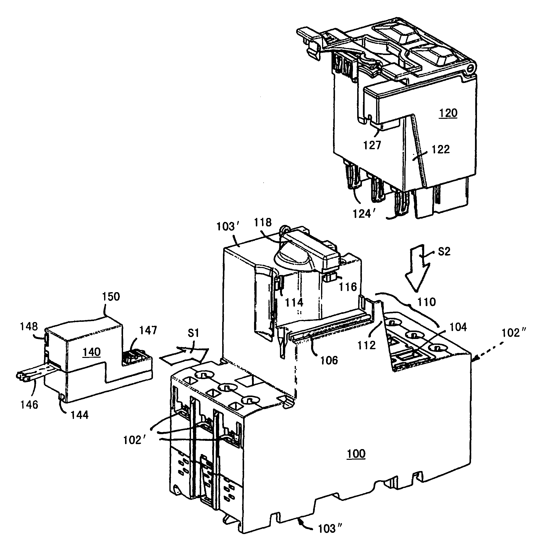
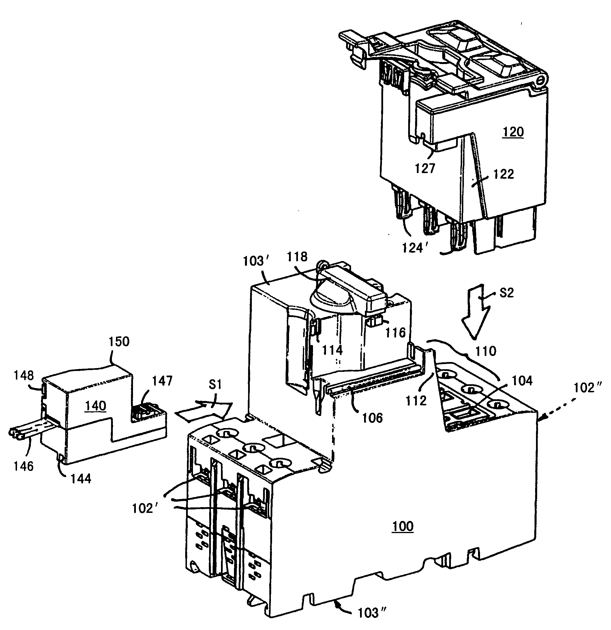
[0027] The figure shows a perspective view of the three elements of the modular system. The invention relates to a protective switching device which is part of a pluggable switching combination, the components of which are constructed according to a building block system. The components of the building block system are (in so far as they are relevant for the invention): switching device basic module 100 , control module 120 and communication module 140 . For plugging the parts of the modular system, there are mechanical guide elements and electrical contact means (plug contacts, contact holders).

[0028] The lower side 103'' of the switching device-basic module 100 is primarily intended for fastening to a chassis, for example a support rail, while its upper side 103' is designed as an operating panel for the operator, in particular equipped with operating knobs and display device.

[0029] The switchgear-basic module 100 comprises multi-phase main current paths extending be...


PUM


Abstract

The present invention relates to an electric protective switch device having control electronics, particularly a motor starter for an electric motor, contactor or the like, wherein the control electronics can be linked to a bus system 146 via a communication module 140 and the communication module 140 can be plugged and can be electrically contacted to a control module 120 by contacts 147. According to the invention, the first mechanical guide elements 106 at the switch device base module and the associated mechanical elements 144 at the communication module 140 are designed such that electric contact between the communication module 140 and control module 120 only occurs if in the order of plugging, first the communication module 140 is mechanically connected to the switch device base module 100, and then the control module 120 is plugged onto the switch device base module 100 and communication module 140. The pluggable communication module 140 is designed as an interface between the control electronics and an electronic bus system 146.

Description

technical field [0001] The invention relates to an electrical protective switching device with control electronics, in particular a motor starter for an electric motor, a power protective switch or a protective switch against thermal overload or short-circuit, wherein the control electronics can be connected via an interface module to the bus The system is networked and the interface modules are pluggable by means of contacts. Background technique [0002] Electrical protective switching devices are known, in particular as motor starters or motor protective switches, the control electronics of which can be connected via a communication bus (eg DE 19820667A1, DE 19924413A1, DE 10010290A1). [0003] Other protective switching devices basically include: a basic structural assembly, a manual operating device, an electronic control unit, an actuator unit and a trip unit. At least the switching mechanism is actuated by means of a manual actuating device via a rotary knob and via ...

Claims


Application Information

Patent Timeline
IPC IPC(8): H01H71/02H01H71/74H01H9/22
CPCY04S20/14Y02B90/224H01H9/22H01H71/0228H01H71/7409H01H2071/7472H01H2300/03Y02B90/20
Inventor K·道尔G·鲍扬A·于利希
Owner EATON INDUSTRIES
Why Eureka
Try Eureka