Wind power station with current bus

A power station, wind power technology, applied in the field of current-carrying devices, can solve problems such as high cost

Inactive Publication Date: 2005-02-02
阿洛伊斯沃本
View PDF0 Cites 6 Cited by
  • Summary
  • Abstract
  • Description
  • Claims
  • Application Information

AI Technical Summary

Problems solved by technology

This is a costly work process as the cables have to be installed over the height of the entire tower in a single work cycle

Method used


Image

  • Wind power station with current bus
  • Wind power station with current bus
  • Wind power station with current bus

Examples


Embodiment Construction

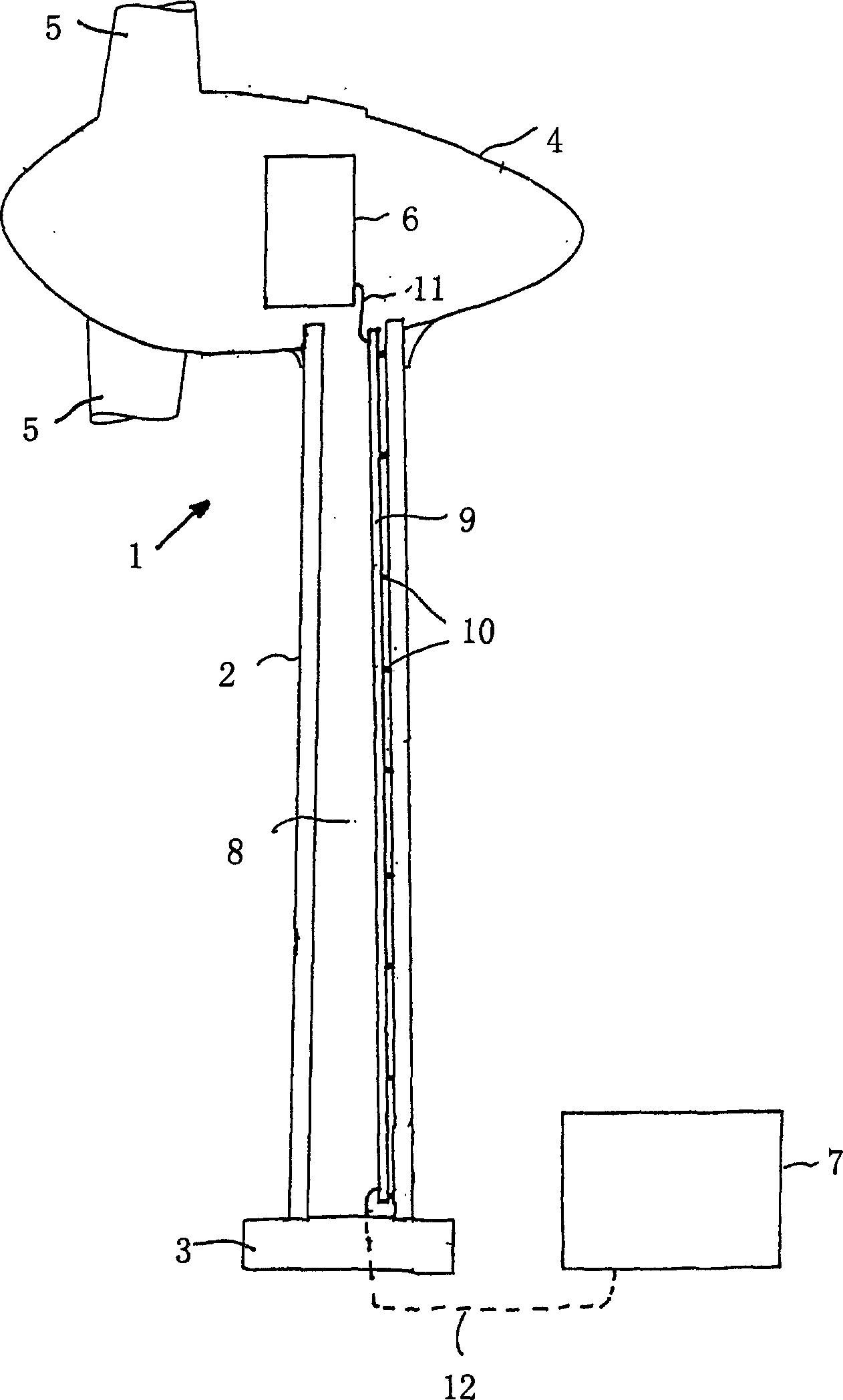
[0015] figure 1 Shown is a schematic diagram of a wind power plant 1 of the present invention, the wind power plant 1 includes a tower 2 with a base 3, a pod 4 rotatably arranged on the top of the tower, and a power module 7 arranged at the base of the tower, such as in a separate room. A rotor with several rotor blades 5 and a generator 6 are arranged in the nacelle 4, the rotor being rotatable about a horizontal axis. Wind energy acts on the rotor blades 5 to rotate the rotor and drive the generator 6 to generate electricity.

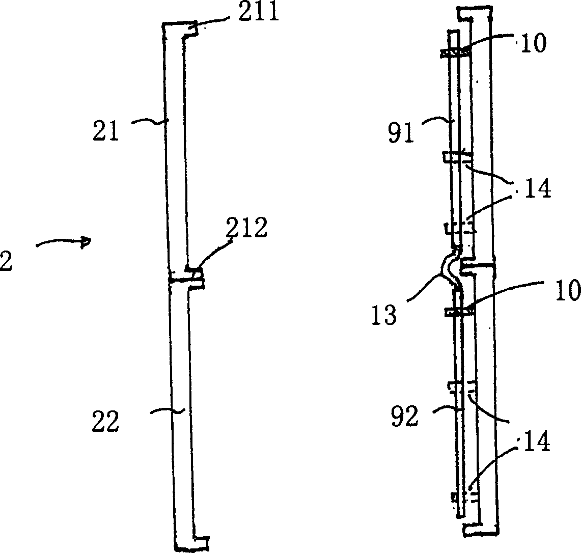
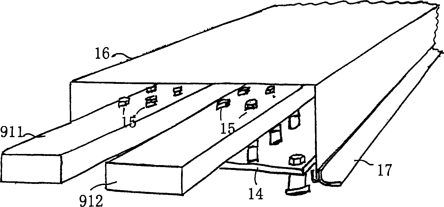
[0016] In order to transfer the energy generated by the generator 6 to the power module 7, which has a number of electrical units, such as a transformer or an optional rectifier, for processing the current before it is transmitted to the grid or to the user, by means of the fastening device 10 On the walls of the interior space 8 of the column 2 there are bus lines, preferably two bus lines. These buses are in electrical conduction or electrical co...


PUM


Abstract

The present invention concerns a wind energy plant for generation of alternating current with a tower constructed of several tower segments, a generator arranged in the region of the top of the tower, a power module arranged in the region of the base of the tower, and current carrying means for transferred current from the generator to the power module. In order to enable faster, easier and thereby cheaper erection of the wind energy plant, it is provided in accordance with the present invention that the current carrying means be premounted in the tower segments in segmented form.

Description

technical field [0001] The present invention relates to a wind power station with a tower with a plurality of tower levels, a generator arranged in the tower top area, a power module arranged in the tower base area, and a power module for transmitting current from the tower top to the power The current carrying device of the module. Background technique [0002] A power module of a wind power station, including electrical units such as transformers, control boxes, optional rectifiers, medium-voltage equipment, and low-voltage power distribution equipment. In existing wind power stations, it is arranged under the generator and is usually set In the tower base area of ​​the wind power station. Most commonly, outside the wind power plant, there is an independent small building to accommodate the module or some components. The current-carrying device is mostly laid in the tower in the form of a cable, and is used to transmit the electrical energy generated by the generator in ...

Claims


Application Information

Patent Timeline
Patent Type & Authority Applications(China)
IPC IPC(8): F03D9/00F03D9/25F03D11/00F03D13/10F03D80/00F03D80/80
CPCF05B2240/912Y02E10/722F03D11/00Y02E10/728H02G5/002F03D80/00F03D9/255F05B2240/14F05B2240/95Y02E10/727F03D80/85F03D13/10F03D9/25F03D80/82Y02E10/72
Inventor 艾劳埃斯·乌本
Owner 阿洛伊斯沃本
Why Eureka
Try Eureka