Bone screw

A technology of bone screw and thread, applied in the direction of internal bone synthesis, fixer, fastening device, etc., can solve the problem of inappropriate intubation, and achieve the effect of promoting the healing process

Inactive Publication Date: 2011-06-08
BIEDERMANN TECH GMBH & CO KG
View PDF10 Cites 11 Cited by
  • Summary
  • Abstract
  • Description
  • Claims
  • Application Information

AI Technical Summary

Problems solved by technology

The cannula is not suitable for fill

Method used


Image

  • Bone screw
  • Bone screw
  • Bone screw

Examples


Example Embodiment

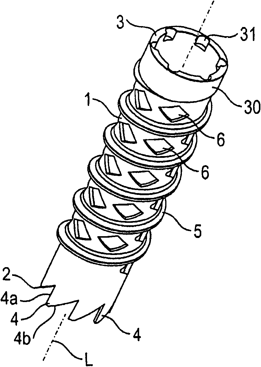
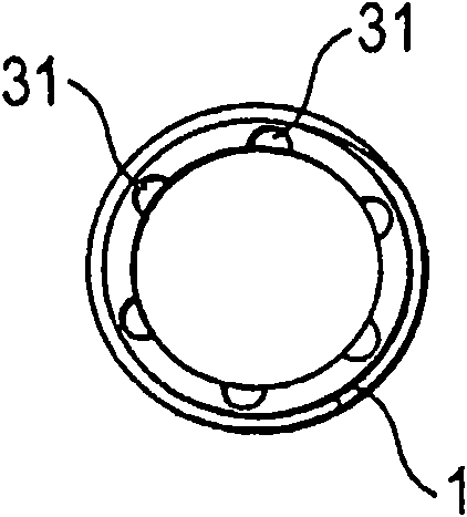
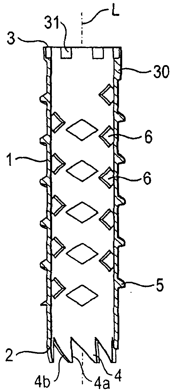
[0021] Such as Figure 1-4 The bone screw according to the first embodiment shown in includes a tubular body 1 having an open first end 2 and an open second end 3 and a central longitudinal axis L. At the first end 2, the free edge of the tubular body includes a plurality of cutting teeth 4 configured to cut holes in the bone. In a part of the outer wall of the tubular body (as shown in this embodiment, this part is close to the first end 2), the tubular body includes a so-called bone thread 5. The bone thread 5 is configured to cut into the bone when the bone screw is screwed into the bone. Although the drawings show bone threads having a substantially serrated shape, all types of known bone threads can be used. The cutting teeth 4 extend coaxially with the longitudinal axis L from the edge of the first end 2. In the illustrated embodiment, the cutting teeth are substantially saw-tooth shaped. This shape includes a steep flank 4a and a shallow flank 4b, wherein the steep f...


PUM


Abstract

The present invention provides a bone screw including a tubular body (1) with a bone thread (5) in at least a portion of its outer wall, the tubular body having an open first end (2) and an open second end (3); wherein at the open first end (2) a plurality of cutting teeth (4) is provided and wherein at the second end (3) a structure (31, 310) for engagement with a screwing-in tool (100) is provided. The invention also provides a tool used for being inserted into the bone screw, wherein the tool includes a structure (102, 103) for engagement that join with the structure (31, 310) for engagement of the bone screw to form a guide thread.

Description

technical field [0001] The present invention relates to bone screws. In particular, the present invention relates to bone screws that can be used as fusion screws. Such screws promote fusion in the surrounding bone. Background technique [0002] A bone screw of this type is known from US2004 / 0015172A1. The bone screw has a tubular threaded portion with bone threads and grooves in its wall. The head and tip are connectable to the tubular threaded portion. In use, the tubular portion can be filled with bone material or other growth promoting material and then the tip and / or head are connected to the tubular portion. First, a core hole is prepared, then a screw is inserted into the core hole and screwed into the bone. After a certain period of time, fusion occurs between the screw and bone. The screw can act as a distraction element so that comminuted or split parts of bone are joined together by the screw. To avoid the preparation of a core hole, the tip can be self-cut...

Claims


Application Information

Patent Timeline
IPC IPC(8): A61B17/86
CPCA61B17/8635A61B17/862A61B17/8897A61B17/8875A61B17/864A61B17/8883
Inventor L・比德曼W・马蒂斯J・哈姆斯
Owner BIEDERMANN TECH GMBH & CO KG
Why Eureka
Try Eureka