Circuit signal detection device

A signal detection and circuit technology, which is applied in the field of circuit signal detection devices, can solve the problems of not comprehensively testing the correctness and complexity of signals

Inactive Publication Date: 2011-06-08
洪明
View PDF5 Cites 3 Cited by
  • Summary
  • Abstract
  • Description
  • Claims
  • Application Information

AI Technical Summary

Problems solved by technology

[0002] There are many methods for circuit signal testing, some are cumbersome, some require powerful equipment, and in some occasions, the correctness of the circuit is very high, and many tests are for specific output under specific input conditions. Test the correctness of the signal

Method used


Image

  • Circuit signal detection device
  • Circuit signal detection device
  • Circuit signal detection device

Examples


Embodiment Construction

[0030] Below in conjunction with accompanying drawing, specific embodiment of the present invention and working principle are described further:

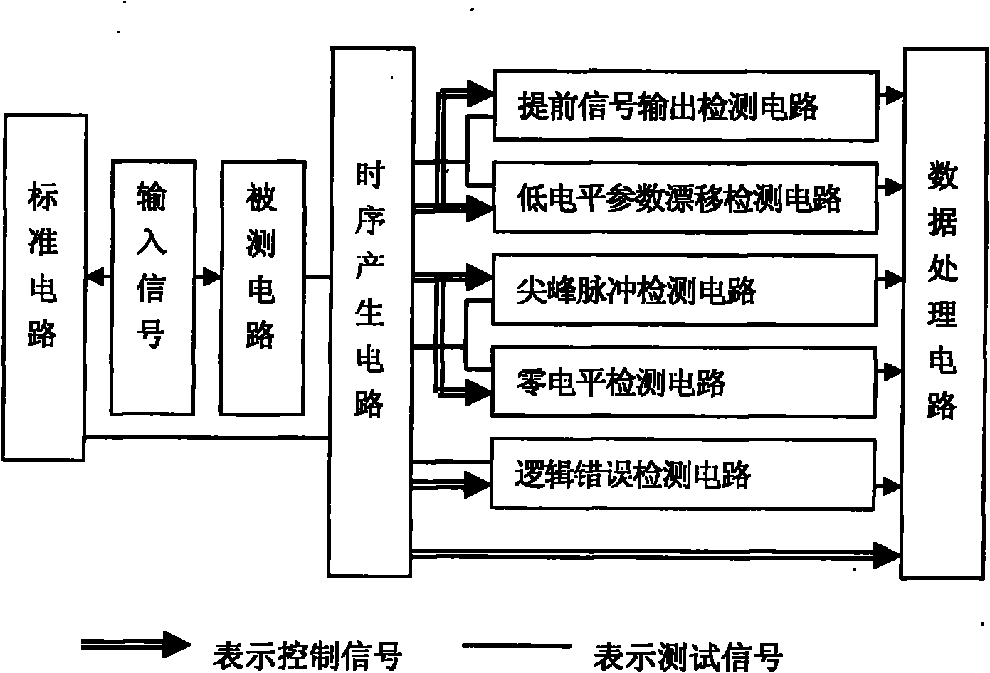
[0031] figure 1 It is the functional block diagram of the circuit signal detection device. Depend on figure 1 It can be seen that the circuit signal detection device is composed of a timing generation circuit, an advance signal output detection circuit, a spike detection circuit, a logic error detection circuit, and a data processing circuit. The device also has a low-level parameter drift detection circuit and a zero-level detection circuit.

[0032]The input terminals of the standard circuit and the circuit under test are connected, and the same input signal is applied at the same time, the output of the standard circuit and the circuit under test are connected with the timing generation circuit, and the output of the timing generation circuit is connected with the advance signal detection circuit and the low level parameter resp...


PUM


Abstract

The invention relates to a circuit signal detection device for detecting an electrical signal. The device comprises a time sequence generating circuit, an advance signal output detection circuit, a peak pulse detection circuit, a logical error detection circuit and a data processing circuit. By applying the same test conditions to a standard circuit and a detected circuit at the same time and conducting work, comparison test on the output signals of the standard circuit and the detected circuit as well as comparison test control are performed by use of adjustment of the output time sequences of the detected circuit and the standard circuit; and the advance signal output detection circuit, the peak pulse detection circuit, the logical error detection circuit, a low-level parameter shift detection circuit and the data processing circuit detect whether the advance signal output, peak pulse output, logical error output, low-level parameter shift and zero-level output exist on the detectedcircuit so as to check correctness of the output signal.

Description

technical field [0001] The invention relates to a circuit signal detection device for electric signal detection. Background technique [0002] There are many methods for circuit signal testing, some are cumbersome, some require powerful equipment, and in some occasions, the correctness of the circuit is very high, and many tests are for specific output under specific input conditions. Test the correctness of the signal. Contents of the invention [0003] The invention provides a simple signal correctness detection device for the problems of early signal output, peak pulse, logic error and parameter drift of the circuit. [0004] The technical scheme of the present invention is: the circuit signal detection device is composed of a timing sequence generation circuit, an advance signal output detection circuit, a peak pulse detection circuit, a logic error detection circuit, and a data processing circuit, and a standard circuit with the same structure and the same design as ...

Claims


Application Information

Patent Timeline
Patent Type & Authority Applications(China)
IPC IPC(8): G01R31/28
Inventor 洪明洪启媛林中昊林日其
Owner 洪明
Why Eureka
Try Eureka