

Method for controlling the vacuum generator in a vacuum sewage system
A technology of vacuum generator and control method, which is applied in the direction of waterway system, pump control, sewage discharge, etc., and can solve problems such as low efficiency, liquid ring failure, generator loss, etc.
- Summary
- Abstract
- Description
- Claims
- Application Information
AI Technical Summary
Problems solved by technology
Method used
Image

Examples
Embodiment Construction
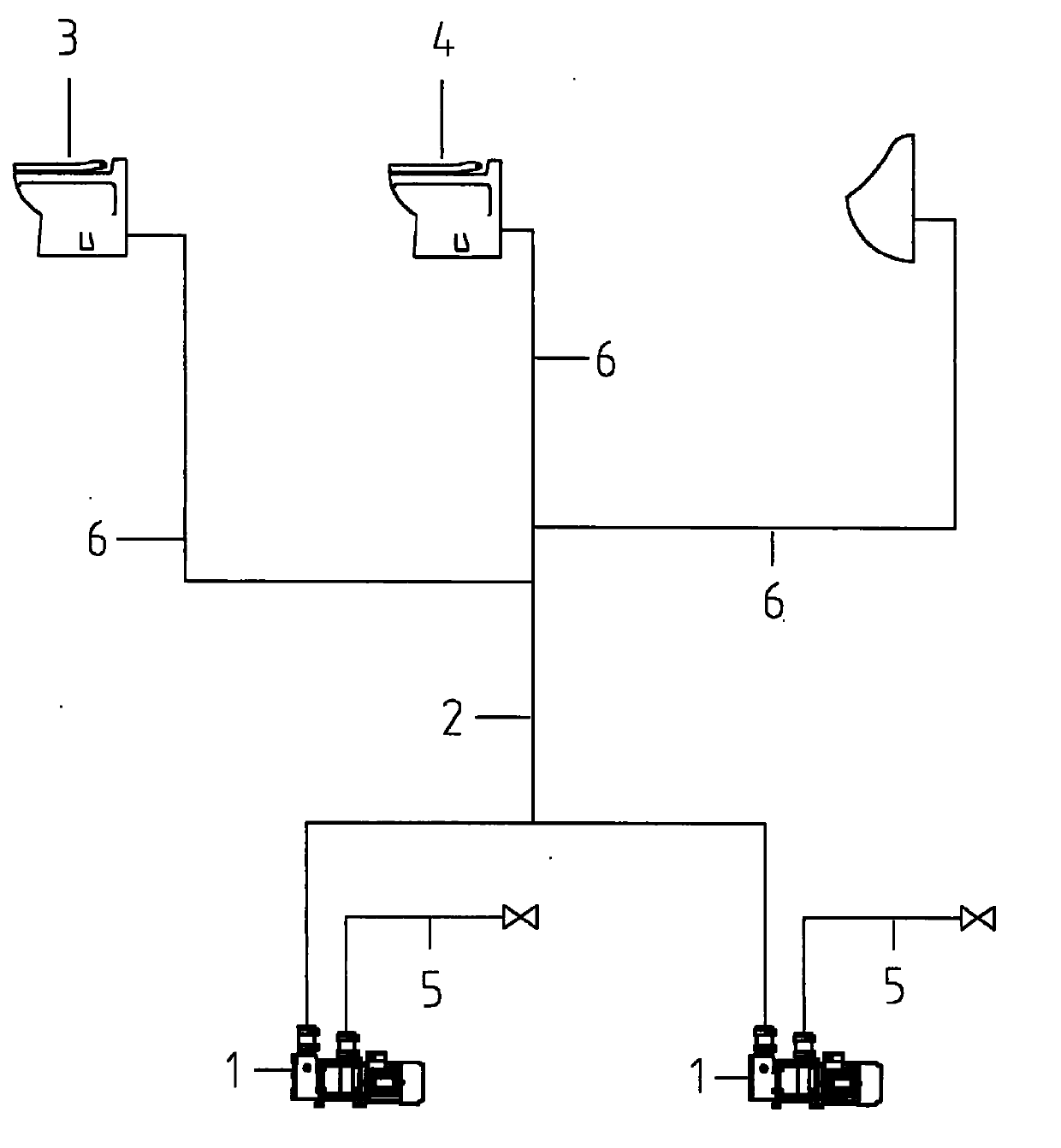
[0012] As mentioned above, figure 1 An example of a vacuum drainage system is shown comprising two vacuum generators 1 connected in parallel in the form of liquid ring screw pumps with integrated macerators, a common suction line or collection pipe 2, connected at one end to a vacuum The generator is also connected with a plurality of toilets, urinals 3, 4, etc. through the branch pipeline 6 at the other end. When flushing the toilet or urinal, etc., the vacuum generator 1 generates a vacuum in the common suction line 2 and the branch line 6, continuously sucks and fills liquid and air into the generator, and discharges it through the outlet 5 of the generator.
[0013] As mentioned above, figure 1 The system shown is normally controlled by the on / off operation of the vacuum generator. Therefore, when the system is in a low mode state of use, for example, at midnight, with only a few or no toilets being used, only A vacuum generator is running. Once the vacuum generator re...
PUM
 Abstract
Description
Claims
Application Information