

Ribbon cartridge
A technology of ribbon box and ribbon, which is applied in the field of ribbon box, can solve the problems of shortened life of ribbon and damaged printing, etc.
Active Publication Date: 2011-06-15
PRINT RITE UNICORN IMAGE PROD CO LTD OF ZHUHAI
View PDF5 Cites 7 Cited by
- Summary
- Abstract
- Description
- Claims
- Application Information
AI Technical Summary
Problems solved by technology
Aiming at the problem that the above-mentioned color ribbon box is prone to print damage at the welding part of the color ribbon, resulting in shortened life of the color ribbon, the purpose of the present invention is to provide a color ribbon box used in dot matrix printers
Method used
View moreImage
Smart ImageViewing Examples

Examples
Embodiment Construction
Login to View More PUM
 Abstract
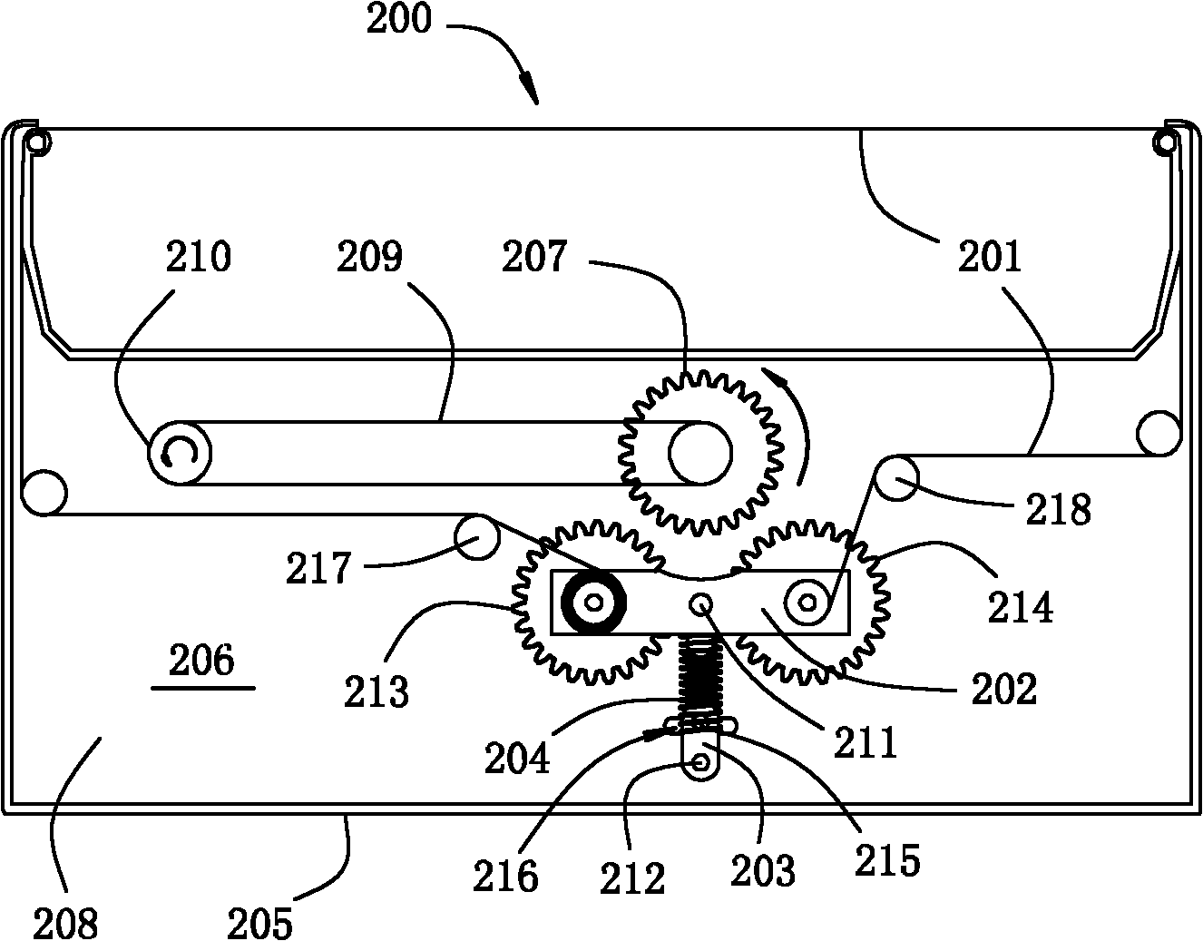
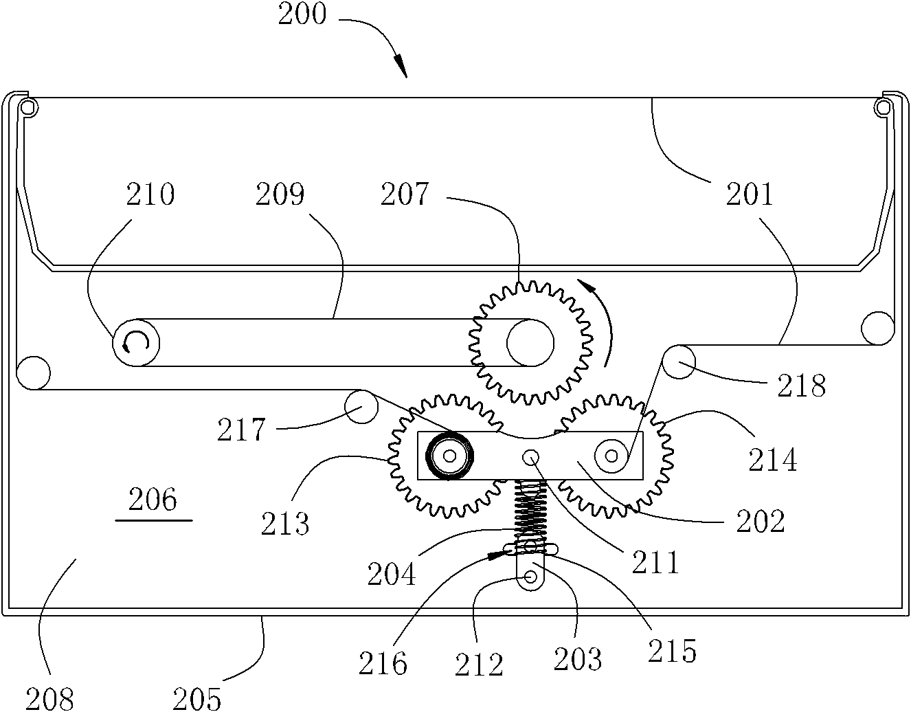
The invention discloses a ribbon cartridge applied to a needle printer. The ribbon cartridge comprises a ribbon, a seesaw, a connecting rod and a cartridge body. A driving gear is arranged in the cartridge body; the seesaw is rotatably fixed on a first supporting point; a first transmission gear and a second transmission gear are fixed at two ends of the seesaw in a rotatable mode; the connecting rod is rotatably fixed on a second supporting point; a locking block on the connecting rod is inserted into a chute on the cartridge body and can slide; the first supporting point and the second supporting point are positioned on the cartridge body; the first supporting point is positioned between the second supporting point and the driving gear; a compressed spring is fixed between the connecting rod and the seesaw; a first ribbon passing shaft and a second ribbon passing shaft are arranged in the cartridge body; two ends of the ribbon respectively run around either the first ribbon passing shaft or the second ribbon passing shaft and are fixed on middle shafts of the first and second transmission gears; a part of the ribbon positioned between the first ribbon passing shaft and the first transmission gear and a part of the ribbon positioned between the second ribbon passing shaft and the second transmission gear are positioned on one side of the first supporting point facing the driving gear along the direction of a connecting line of the first supporting point and the driving gear. The ribbon cartridge can effectively improve the service life of the ribbon.
Description
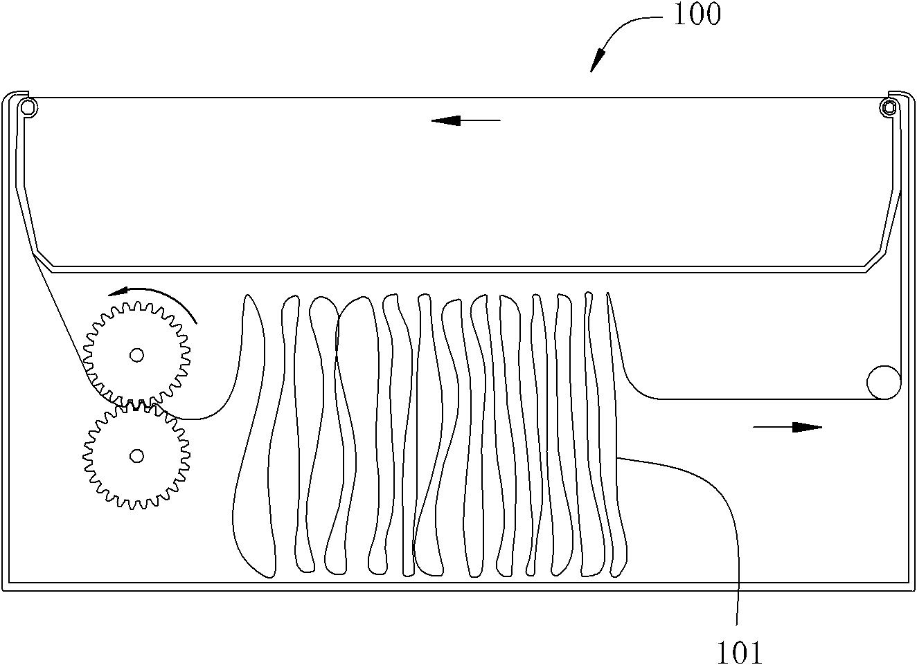
ribbon box technical field The invention relates to a color ribbon box, especially a color ribbon box used for accommodating a color ribbon and providing coloring media for dot matrix printers. Background technique As shown in Fig. 1, the existing ribbon cartridge 100 applied to dot matrix printers is used as a coloring medium, or in other words, the ribbon 101 with ink permeated thereon is generally made of a soft and strong fiber strip, usually in the form of an endless loop. The production of endless belts is achieved by lapping and welding the two ends of the elongated ribbons together. This structural feature of the annular belt makes the structure and performance of the welded part different from other parts, or the thickness and density of the welded part of the ribbon are greater than that of other non-welded parts, or because it has experienced high temperature and high pressure treatment , leading to the destruction of the material structure characteristics of t...
Claims
Login to View More Application Information
Patent Timeline
 IPC IPC(8): B41J32/00
CPCB41J32/00
Inventor李宝生
OwnerPRINT RITE UNICORN IMAGE PROD CO LTD OF ZHUHAI