Combined multi-blade saw device and sawing method

A multi-blade saw and wood technology, applied in the direction of feeding devices, circular saws, sawing components, etc., can solve the problems of not being able to dissipate heat in time, the saw blade bears a large load, and has a lot of heat, and achieves a convenient, fast and reliable installation method. Improve work efficiency and cooperate scientifically

Active Publication Date: 2017-06-23
HEILONGJIANG LINKE WOODEN PROD
View PDF10 Cites 0 Cited by
  • Summary
  • Abstract
  • Description
  • Claims
  • Application Information

AI Technical Summary

Problems solved by technology

[0004] At present, the equipment used for sawing wood adopts the method of sawing off or sawing the wood at one time. If the height of the wood sawing road is too high, the saw blade will bear a large load, and a lot of heat will be generated during the sawing process and cannot be dissipated in time, which will cause the saw blade to be easily damaged. Damage, causing deviation, loss of sawn timber, increased cost of sawn timber

Method used


Image

  • Combined multi-blade saw device and sawing method
  • Combined multi-blade saw device and sawing method
  • Combined multi-blade saw device and sawing method

Examples


Embodiment 1

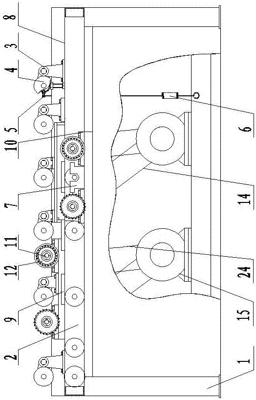
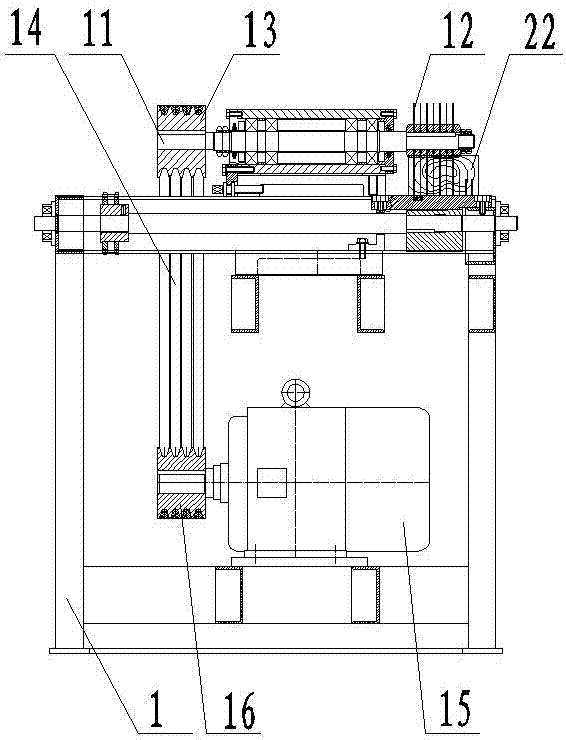
[0024] A combined multi-blade saw device, which consists of: a base 1, a workbench 2 is installed above the base, and a set of auxiliary wheels 3 and a set of feeding parts 4 are installed on the upper part of the workbench. The feeding part is connected to one end of the spring 6 through the connecting bolt 5, and the other end of the spring is connected to the lower part of the machine base. A group of brackets 7 are installed on the lower part of the workbench, and the feeding part is mounted on the bracket. , the described workbench is provided with a feeding platform 8, a group of guide plates 9 are installed on the described feeding platform, a group of bearing blocks 10 are installed on the described workbench, a saw shaft 11 is housed in the described bearing block, the described One group of saw blades 12 is equipped with one end of the saw shaft, and the shaft pulley 13 is equipped with the other end, and described shaft pulley is connected with the power output wheel...

Embodiment 2

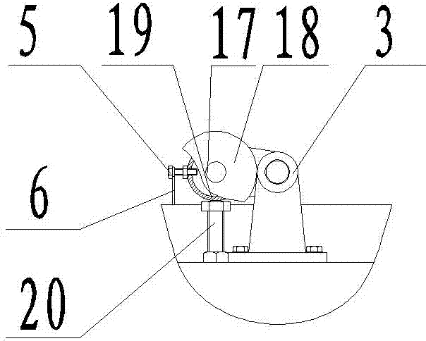
[0026] According to the combined multi-blade saw device described in Embodiment 1, the feeding part includes a feeding shaft 17, a feeding roller 18 is installed at the end of the feeding shaft, and a shaft seat 19 is installed outside the feeding shaft. The connecting spring is installed on the shaft seat, and the workbench is equipped with adjusting bolts 20 at corresponding positions below the shaft seat, and the bottom surface of the shaft seat is in contact with the adjusting bolts.

Embodiment 3

[0028] According to the combined multi-blade saw device described in Embodiment 1, the guide plate is fixed on the feeding platform through the extrusion of the mounting block 21, and the position of the guide plate corresponds to the saw edge 23 of the wood 22; The feeding shaft and the auxiliary wheel are connected with the power take-off wheel through a chain 24 .


PUM


Abstract

The invention discloses a combined multi-blade saw device and a sawing method. A large amount of heat energy is produced in a sawing process of saw blades during the operation of equipment used for sawing so that quick damage of the saw blades is caused in the prior art. The method comprises the steps that a workbench (2) is mounted above a base (1); a group of auxiliary wheels (3) and a group of feeding parts (4) are mounted on the upper part of the workbench; the feeding parts are connected with one end of a spring (6) through a connecting bolt (5); the other end of the spring is connected with the lower part of the base; a group of supports (7) are mounted on the lower part of the workbench; the feeding parts are mounted on the supports; a feeding platform (8) is arranged on the workbench; a group of guiding plates are mounted on the feeding platform; a group of bearing seats (10) are mounted on the workbench; saw shafts (11) are mounted in the bearing seats; a group of saw blades (12) are mounted at one ends of the saw shafts; shaft belt pulleys (13) are mounted at the other ends of the saw shafts and are connected with power output wheels (16) of motors (15) mounted on the base. The combined multi-blade saw device is used for sawing.

Description

[0001] Technical field: [0002] The invention relates to a combined multi-blade saw device and a sawing method. [0003] Background technique: [0004] At present, the equipment used for sawing wood adopts the method of sawing off or sawing the wood at one time. If the height of the wood sawing road is too high, the saw blade will bear a large load, and the heat will be generated during the sawing process and cannot be dissipated in time, which will make the saw blade easy to Damage, causing deviation, loss of sawn timber, and increased cost of sawn timber. [0005] Invention content: [0006] The object of the present invention is to provide a combined multi-blade saw device and sawing method. [0007] Above-mentioned purpose realizes by following technical scheme: [0008] A combined multi-blade saw device, which consists of: a machine base, a worktable is installed above the machine base, a set of auxiliary wheels and a set of feeding parts are installed on the upper par...

Claims


Application Information

Patent Timeline
Patent Type & Authority Patents(China)
IPC IPC(8): B27B5/02B27B27/00B27B25/00
CPCB27B5/02B27B5/22B27B5/29B27B25/02B27B27/00
Inventor 梁进义
Owner HEILONGJIANG LINKE WOODEN PROD
Why Eureka
Try Eureka