Check patentability & draft patents in minutes with Patsnap Eureka AI!

Optical type position detection device, hand device and touch panel

一种检测装置、光学式的技术,应用在测量装置、采用光学装置传递传感构件、转换传感器输出等方向,能够解决无法正确检测出下陷深度、对象物体与光传播介质界面状态不稳定等问题

Inactive Publication Date: 2011-06-15
SEIKO EPSON CORP
View PDF5 Cites 2 Cited by
  • Summary
  • Abstract
  • Description
  • Claims
  • Application Information

AI Technical Summary

Problems solved by technology

[0007] However, in the technology described in Patent Document 3, when the target object is pressed into the light propagation medium, the state of the interface between the target object and the light propagation medium is not stable regardless of whether reflected light from the target object is detected.
Therefore, in the technology described in Patent Document 3, when the target object is pressed into the light propagation medium (light-transmitting member), there is a problem that the sag depth of the target object (the relative position of the target object with respect to the light-transmitting member) cannot be accurately detected. question

Method used


Image

  • Optical type position detection device, hand device and touch panel
  • Optical type position detection device, hand device and touch panel
  • Optical type position detection device, hand device and touch panel

Examples


Embodiment approach 1

[0034] (overall composition)

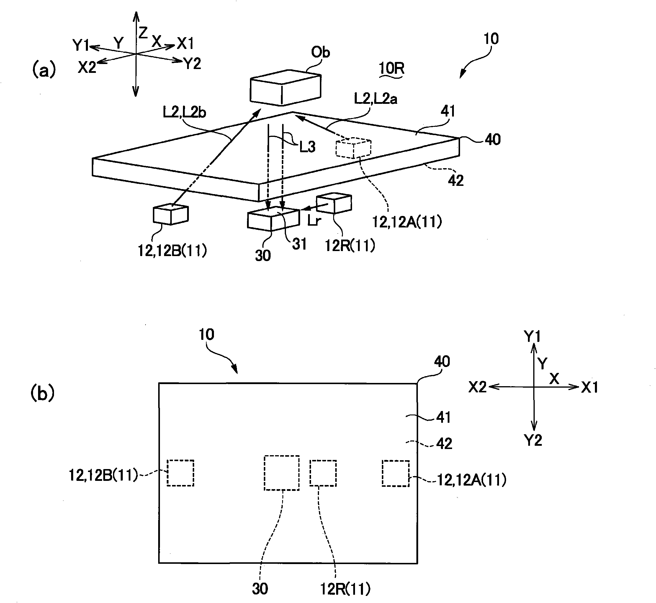
[0035] figure 1 It is an explanatory diagram schematically showing main parts of the optical position detection device according to Embodiment 1 of the present invention, figure 1 (a) and (b) are explanatory diagrams showing the three-dimensional arrangement of the components of the optical position detection device, and explanatory diagrams showing the planar arrangement of the components of the optical position detection device. figure 2 It is an explanatory diagram showing the overall configuration of the optical position detection device according to Embodiment 1 of the present invention. image 3 is an explanatory diagram schematically showing a state where a target object is in contact with a light-transmitting member in the optical position detection device according to Embodiment 1 of the present invention, image 3 (a) and (b) are explanatory diagrams schematically showing a state where a target object is in contact with the light-trans...

Embodiment approach 2

[0105] In Embodiment 1, it was described that in the optical position detection device 10 , in addition to detecting the separation distance between the target object Ob and the light-transmitting member 40 and the contact between the target object Ob and the light-transmitting member 40 using the common photodetector 30 , also detect the in-plane direction position (X coordinate) of the target object Ob, refer to Figure 7-10 , an example of further detecting the YX coordinates of the target object Ob will be described.

[0106] (overall composition)

[0107] Figure 7 It is an explanatory diagram schematically showing main parts of an optical position detection device according to Embodiment 2 of the present invention, Figure 7 (a) and (b) are explanatory diagrams showing the three-dimensional arrangement of the components of the optical position detection device, and explanatory diagrams showing the planar arrangement of the components of the optical position detection d...


PUM


Abstract

The invention provides an optical type position detection device, a hand device and a touch panel. The optical type position detection device can accurately detect the sinking depth of an object when pressing into a light transmission member in an optical mode. In the optical type position detection device (10), a light source device (11) ejects a detection light (L2) from a second face (42) opposite to a first face (41) of the object (Ob) from the light transmission member, and a reflected light (L3) which is reflected by the object (Ob) and is transmitted to the second face (42) of the light transmission member is detected by means of a photodetector (30). The first face (41) of the light transmission part (40) has elasticity and adsorbability in relation to the object (Ob). In the position detection device (10), the sinking depth can be precisely detected at the instant moment when the object (Ob) contacts with the light transmission member (40) and when the object (Ob) presses the light transmission member (40).

Description

technical field [0001] The present invention relates to an optical position detection device for detecting the position of a target object located on one side of a light-transmitting member, and a hand device and a touch panel including the optical position detection device. Background technique [0002] In a hand device mounted on a robot arm, etc., an optical position device that detects the position of a target object is used, and the result of optically measuring the relative position of the target object and the hand is performed. feedback. Conventionally, as such an optical position detection device, an imaging element has been proposed (see Patent Documents 1 and 2). However, an optical position detection device using an imaging element is expensive, and it takes a long time to process an image of an imaging result. Furthermore, it is impossible to detect the strength of the hand holding the target object from the imaging result of the imaging element. [0003] On ...

Claims


Application Information

Patent Timeline
Patent Type & Authority Applications(China)
IPC IPC(8): G06F3/042G01D5/34G06F3/033G06F3/0346G06F3/041
CPCG06F2203/04101G06F3/0425G06F3/042G01D5/34715
Inventor 中西大介
Owner SEIKO EPSON CORP
Features
  • R&D
  • Intellectual Property
  • Life Sciences
  • Materials
  • Tech Scout
  • Unparalleled Data Quality
  • Higher Quality Content
  • 60% Fewer Hallucinations
Learn More