
Variable printing control apparatus and control program

A printing control and variable technology, applied in the direction of digital output to printing unit, input/output process of data processing, instruments, etc., can solve the problems of high processing efficiency, deterioration of processing efficiency, increased processing, etc., and achieve the goal of improving processing efficiency Effect

Active Publication Date: 2014-07-16
KONICA MINOLTA BUSINESS TECH INC
View PDF4 Cites 0 Cited by
  • Summary
  • Abstract
  • Description
  • Claims
  • Application Information

AI Technical Summary

Problems solved by technology

[0005] In the variable printing described above, in the case where one sub-image to be synthesized is stored per page, if the number of sub-images increases, the number of pages to be rasterized becomes large, resulting in a significant deterioration in processing efficiency.
In particular, processing efficiency significantly deteriorates for data consisting of a large number of part maps with a small area of ​​the common part (reuse part map) and data consisting of a large number of variable parts (temporary use part map)
[0006] Therefore, in order to improve the processing efficiency of variable printing, it is desirable not to generate data that causes the deterioration of processing efficiency as described above. However, it is impossible for the user to determine whether data with high processing efficiency or data with low processing efficiency is on the side of the device that controls variable printing.
In addition, there is a problem that such data is likely to be generated even though the user does not intend it, and if such data is input, the processing efficiency will be extremely reduced.
[0007] In addition, in Patent Document 1, processing efficiency can be improved by collectively rasterizing the non-reuse sub-maps (temporary use sub-maps), but a second layout is required for collective rasterization, and a second layout must be generated. 2 The internal information such as the position and size of the layout, so the processing is increased
In addition, in Patent Document 1, since the compositing process of the raster image is absolutely necessary, the processing efficiency will still deteriorate if the number of sub-images increases.

Method used


Image

  • Variable printing control apparatus and control program
  • Variable printing control apparatus and control program
  • Variable printing control apparatus and control program

Examples


Embodiment

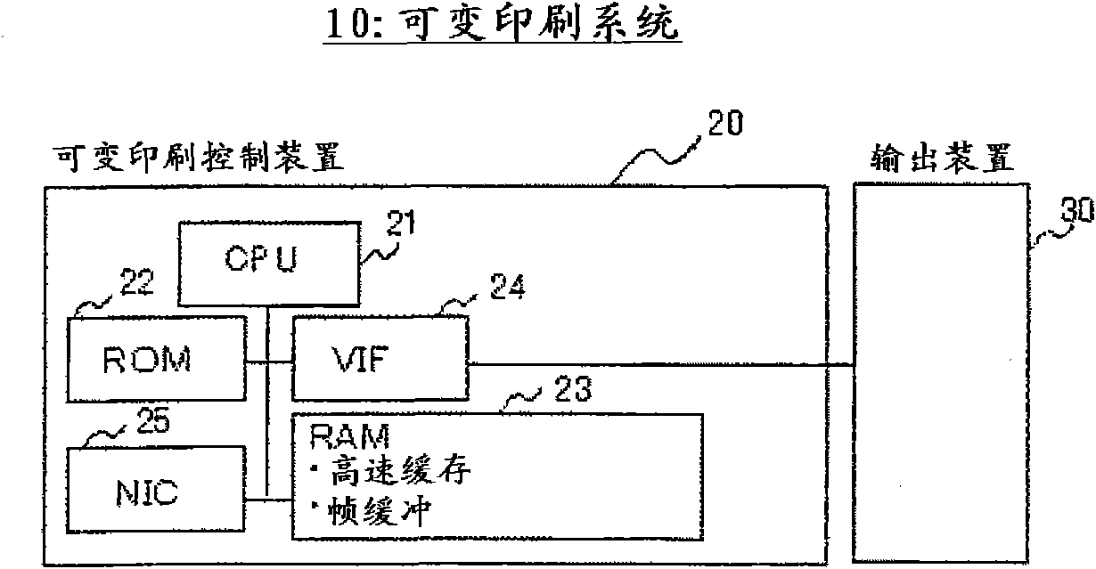
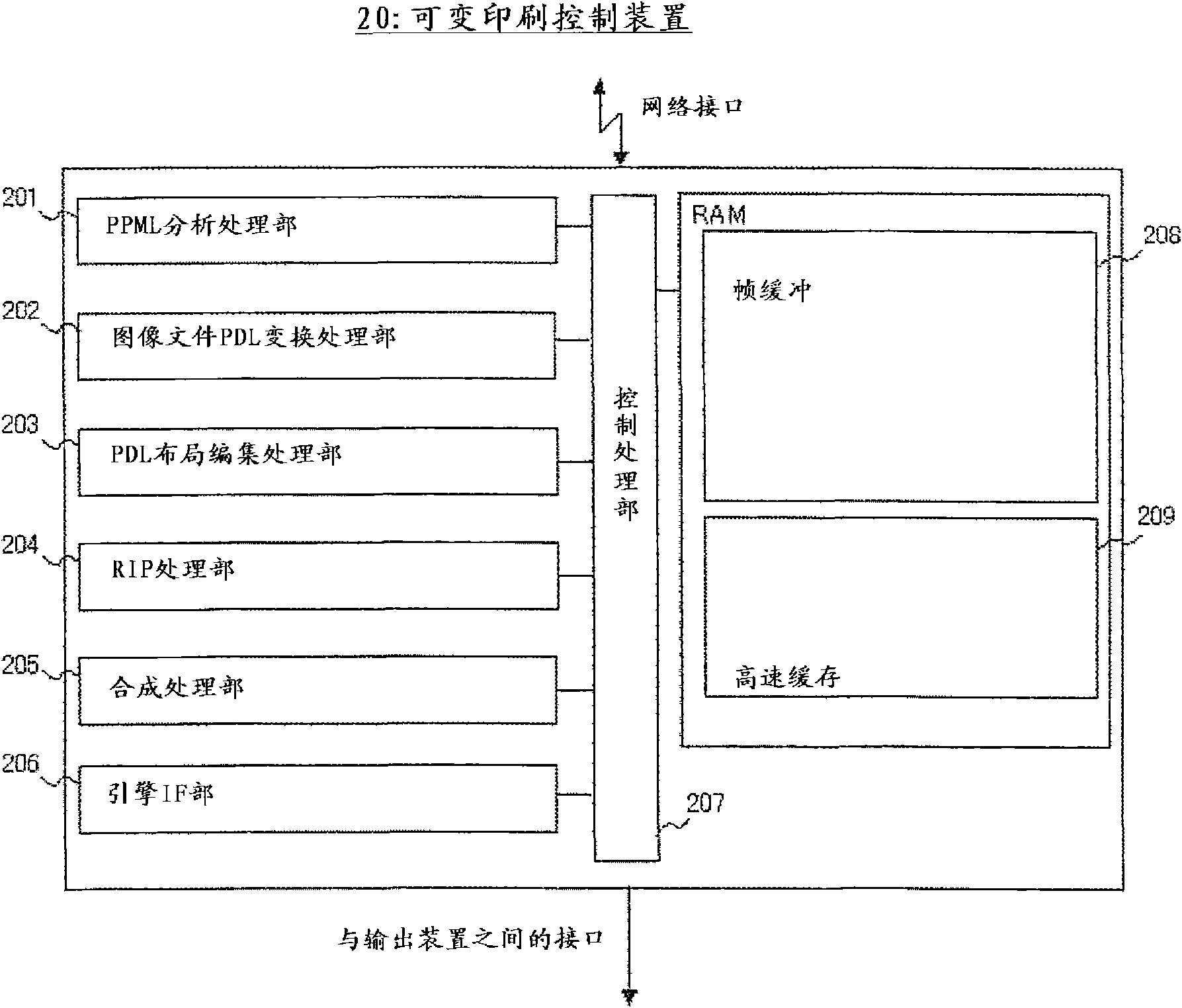
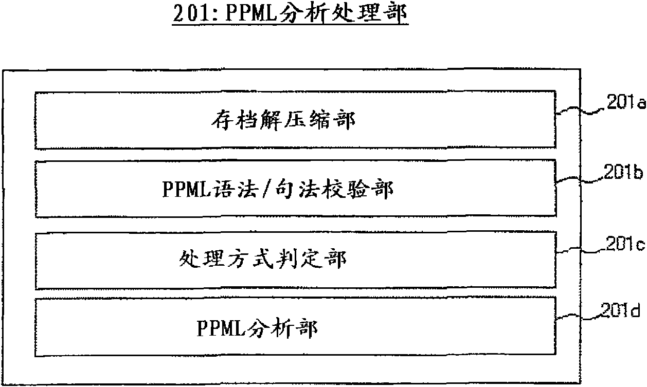
[0031] In order to describe the above-mentioned embodiments of the present invention in more detail, refer to Figure 1 to Figure 11 A variable printing control device and a control program according to an embodiment of the present invention will be described. figure 1 is a block diagram showing the configuration of the variable printing system of this embodiment, figure 2 It is a diagram showing the program structure of the variable printing control device. in addition, image 3 is a block diagram showing the configuration of the PPML analysis processing unit, Figure 4 It is a block diagram showing the configuration of a PDL layout editing processing unit. in addition, Figure 5 as well as Image 6 It is a figure explaining the conventional processing method and the processing method proposed by this embodiment, Figure 7 to Figure 11 It is a flowchart showing the processing of the variable printing control device.

[0032] like figure 1 As shown, the variable print...


PUM


Abstract

A variable printing control apparatus for creating an image data to be printed, using variable printing data containing a plurality of page data in which one of a plurality of parts is arranged in one page, the variable printing control apparatus being configured to implement: a first processing method for rasterizing the plurality of page data, extracting the plurality of parts from each of pieces of raster data, and superimposing the plurality of parts of raster data to create the image data; and a second processing method for converting the plurality of page data into PDL data, extracting the plurality of parts from each of pieces of PDL data, superimposing the plurality of parts of PDL data, and rasterizing the superimposed PDL data to create the image data.

Description

technical field [0001] The present invention relates to a variable printing control device and a control program for controlling variable printing. Background technique [0002] Variable printing is a technique of extracting common parts and reusing them as much as possible, and replacing only variable (variable) parts, thereby saving image generation time. The conventional variable printing is to rasterize the repeatedly used sub-images (hereinafter referred to as reused sub-images) and store them in the internal storage area after rasterization; ) is rasterized and combined with the cached reused image to generate a page image, and the rasterization of the reused image and the transfer of the same data are suppressed, thereby improving processing efficiency. [0003] With regard to such variable printing, for example, the following Patent Document 1 discloses a configuration in which a printed image involving multiple pages is represented by a plurality of image segments ...

Claims


Application Information

Patent Timeline
Patent Type & Authority Patents(China)
IPC IPC(8): G06F3/12
CPCG06F3/1244G06F3/1211G06F3/1243G06F3/1284
Inventor 井上启坂本茂山崎秀幸
Owner KONICA MINOLTA BUSINESS TECH INC
Learn More