Silt retaining and consolidating method for use in debris flow gully ecological engineering and use thereof
A technology of ecological engineering and debris flow, applied in hydraulic engineering, marine engineering, construction, etc., can solve problems such as inability to hold sediment, improve soil structure, improve effectiveness and long-term effectiveness, and reduce sediment sources. Effect
- Summary
- Abstract
- Description
- Claims
- Application Information
AI Technical Summary
Problems solved by technology
Method used
Image
Examples
Embodiment 1
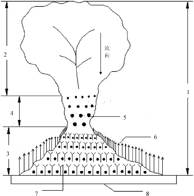
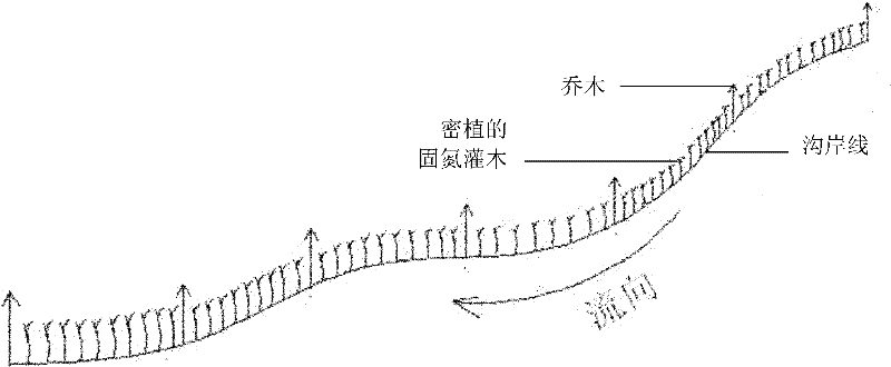
[0025] Such as figure 1 , figure 2 , image 3 , Figure 4 shown. For a valley where a debris flow occurs once in several decades, the ecological engineering sediment retention method of the present invention is directly used in the debris flow valley 1 . The slope of the sediment transport area 4 of the debris flow valley 1 is 10%, and the slope of the bank at the slope foot of the valley 1 is 25 degrees.
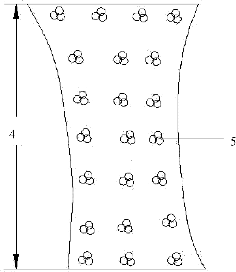
[0026] In the sediment transport area 4 between the debris flow circulation area 2 and the sediment deposition area 3 in the valley 1, plant 8 rows of shrubs 5 to increase the roughness of the ditch bed. sediment. The species of shrub 5 is Masangus sangria, and 3 Masangus sangria are planted together to form shrub 5; the height of shrubs 5 is controlled at 0.8-1.2m; The distance between clusters is 1.5m, and the crown width of shrub 5 is controlled at 0.3×0.3m-0.4×0.4m.
[0027]At the slope foot of the valley 1, a bank protection forest 6 is planted in a linear form...
Embodiment 2
[0030] Such as figure 1 , image 3 , Figure 4 shown. For a valley where debris flow occurs once in a century, the ecological engineering sediment retention method of the present invention is directly used in the debris flow valley 1 . The slope of the sediment transport zone 4 of the debris flow valley 1 is 15%, and the slope of the bank at the slope foot of the valley 1 is 20 degrees.
[0031] In the sediment transport area 4 between the debris flow circulation area 2 and the sediment deposition area 3 in the valley 1, plant 7 rows of shrubs 5 to increase the roughness of the ditch bed. The direction of the rows is perpendicular to the ditch to intercept the upstream transport sediment. The species of bush 5 is selected as bitter thorn, and three bitter thorns are planted together to form bush 5; the height of bush 5 is controlled at 0.8-1.2m; the row spacing between bush 5 is 2.8m, and the same row of The distance between clusters is 1.0m, and the crown width of shrub ...
Embodiment 3
[0035] Such as figure 1 , image 3 , Figure 4 shown. For a valley where a debris flow occurs once in several decades, the ecological engineering sediment retention method of the present invention is directly used in the debris flow valley 1 . The slope of the sediment transport zone 4 of the debris flow valley 1 is 5%, and the slope of the bank at the slope foot of the valley 1 is 30 degrees.
[0036] In the sediment transport area 4 between the debris flow circulation area 2 and the sediment deposition area 3 of the valley 1, plant 9 rows of shrubs 5 to increase the roughness of the ditch bed, and the direction of the rows is perpendicular to the channel to intercept the upstream transport sediment. The species of Shrub 5 are Masangus and Bitterthorn, and 3 Masang plants are planted together to form Shrub 5, and 3 Bitterthorns are planted together to form Shrub 5; the height of Shrub 5 is controlled at 0.8-1.2m; The distance between rows is 3.5m, the distance between bu...
PUM
 Abstract
Description
Claims
Application Information
 - R&D
- Intellectual Property
- Life Sciences
- Materials
- Tech Scout
- Unparalleled Data Quality
- Higher Quality Content
- 60% Fewer Hallucinations
Browse by: Latest US Patents, China's latest patents, Technical Efficacy Thesaurus, Application Domain, Technology Topic, Popular Technical Reports.
© 2025 PatSnap. All rights reserved.Legal|Privacy policy|Modern Slavery Act Transparency Statement|Sitemap|About US| Contact US: help@patsnap.com


