Spot welding machine

A spot welding machine and stand technology, applied in welding equipment, resistance welding equipment, metal processing equipment, etc., can solve the problems of frequent adjustment, easy wear of the lower electrode, large randomness, etc., so as to avoid quality accidents and improve production. Efficiency and the effect of ensuring spot welding quality

Active Publication Date: 2011-07-06
NINGBO MINTH AUTOMOTIVE PARTS RES&DEV CO LTD
4 Cites 28 Cited by

AI-Extracted Technical Summary

Problems solved by technology

[0003] In the process of realizing the above spot welding, it is found that the lower electrode of the spot welding machine is easy to wear, which leads to virtual welding in the spot welding process, which directly affects the quality of the product after welding
Although this defect can adjust the height of the lower ...

Abstract

The invention relates to a sot welding machine, which is improved on the basis of a conventional fixed platform, an upper electrode and a lower electrode. The sot welding machine comprises a table surface and a driving mechanism, wherein a work piece to be welded is placed on the table surface; the driving mechanism drives the table surface to lift and descend; the table surface is positioned between the fixed platform and the upper electrode; and a through hole opposite to the lower electrode is formed on the table surface. When the spot welding machine is used for spot welding, the descending of the table surface can be controlled by applying the upper electrode to the work piece to be welded; and when the work piece to be welded is contacted with the lower electrode for spot welding, the table surface stops descending as long as the upper electrode stops moving down. Therefore, by adopting the spot welding machine, compensation can be obtained automatically by the descending of thetable surface, so that production efficiency is improved greatly, the quality of spot welding is ensured, and a quality accident caused by human factors is avoided by a mode of adjusting the height of the lower electrode without a person; and the sot welding machine is characterized by simple structure, good generality and low modification cost.

Application Domain

Resistance welding apparatus

Technology Topic

EngineeringSpot welding +1

Image

  • Spot welding machine
  • Spot welding machine
  • Spot welding machine

Examples

  • Experimental program(1)

Example Embodiment

[0016] The present invention will be described in further detail below in conjunction with the embodiments of the drawings.
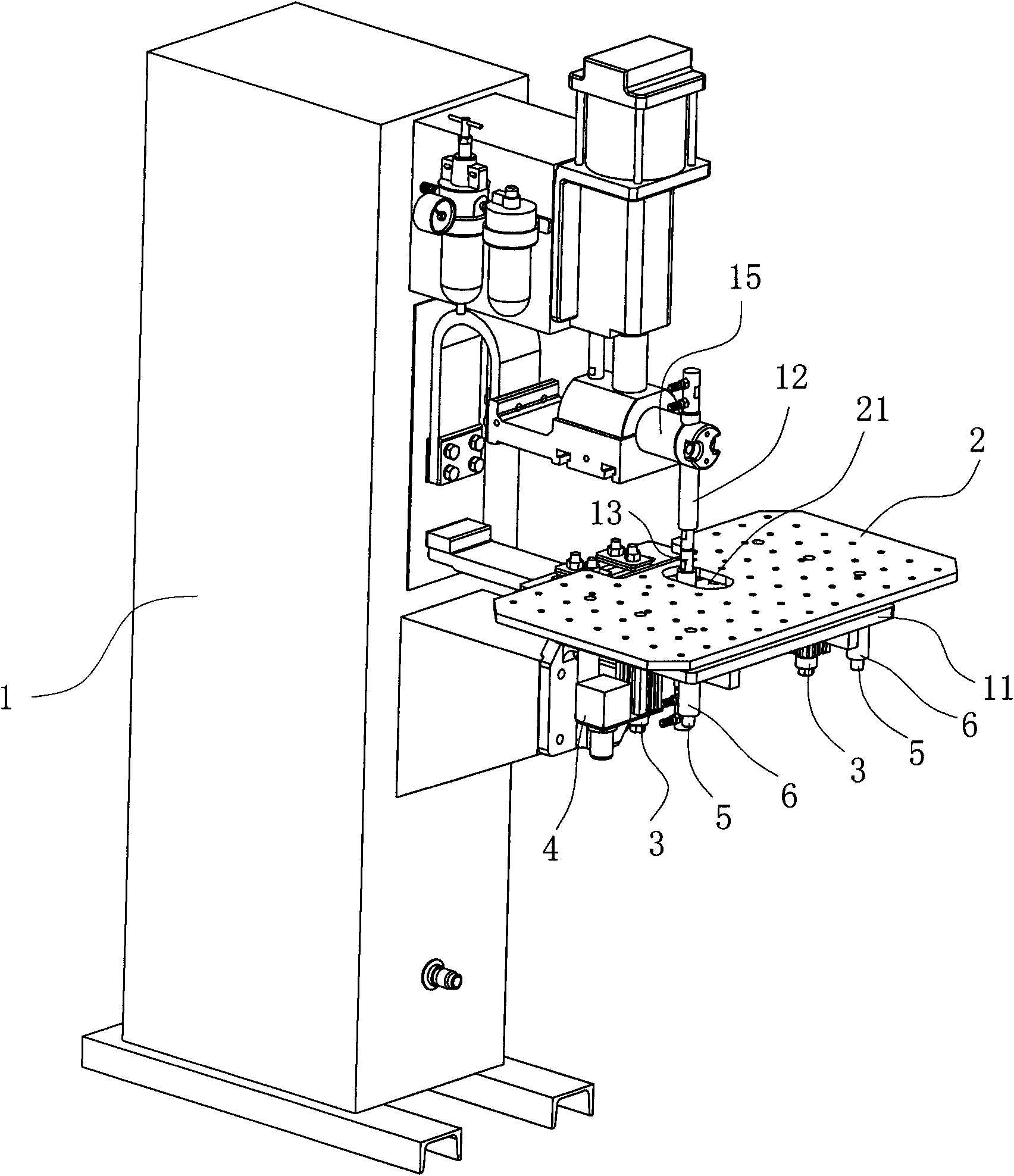
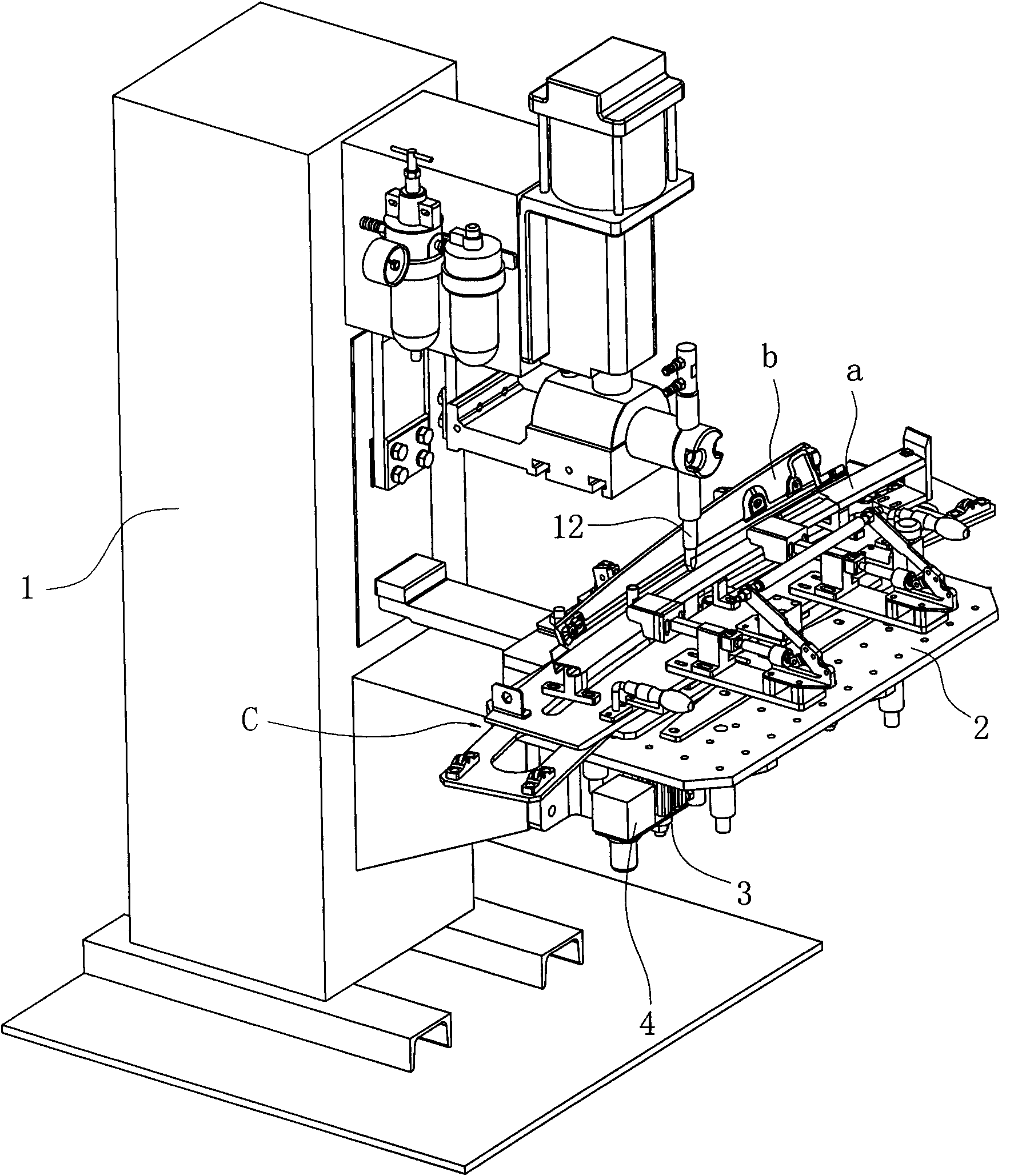
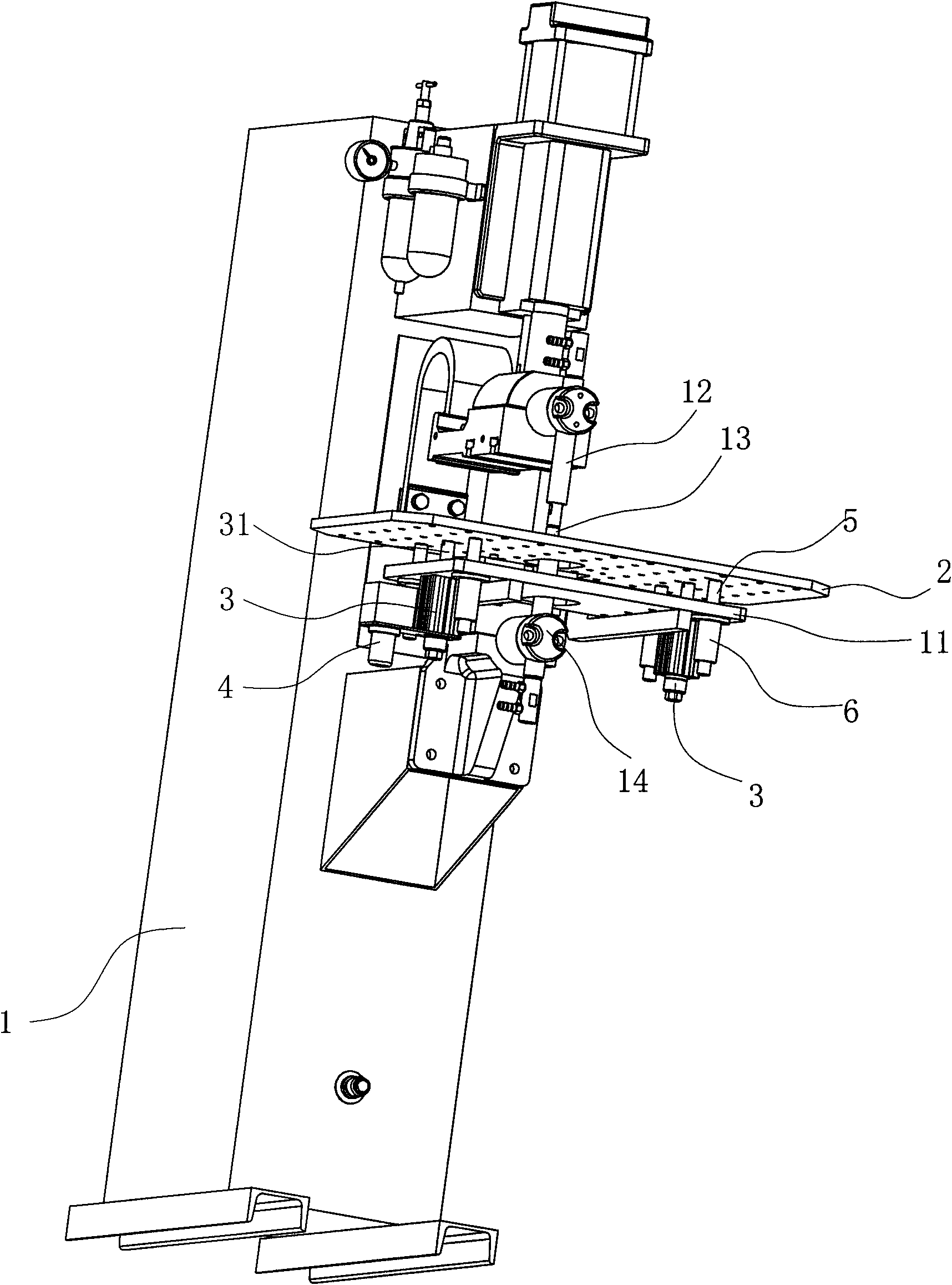
[0017] Such as Figure 1 to Figure 4 As shown, the spot welding machine of this embodiment is used to weld the inner plate a and the outer plate b of an automobile door frame column. The spot welding machine includes a vertical machine base 1, a fixed platform 11, and an upper electrode 12 and a lower electrode corresponding to each other. 13. Wherein, the fixed platform 11 is set on the machine base 1, and its middle part is opened with a through hole opposite to the lower electrode 13; the lower electrode 13 is fixed on the machine base 1 of the spot welding machine through the lower grip bar 14, and the upper end is inserted in In the through hole of the fixed platform; the upper electrode 12 and the upper grip rod 15 can be raised and lowered above the fixed platform under the action of the driving source. Here, the base, the workbench, the driving source, and the upper and lower electrodes all adopt the structure of the existing ordinary spot welding machine. These are all existing technologies and will not be repeated here.
[0018] The invention of this embodiment lies in the addition of a floating platform. The floating platform includes a platform 2 and a driving mechanism that drives the platform up and down. The platform 2 is located between the fixed platform 11 and the upper electrode 12 of the spot welder, and the platform is open. There is a through hole 21 opposed to the lower electrode 13 of the spot welder.
[0019] The above-mentioned driving mechanism is two cylinders 3 arranged side by side, the top of the piston rod 31 of each cylinder is fixed to the bottom surface of the table 2, and the rodless cavity of each cylinder is connected with a pneumatic pressure reducing valve 4 at the same time, and the rodless of the two cylinders The cavity is also connected to a gas source (not shown in the figure) through a bypass (not shown in the figure).
[0020] In order to make the table surface rise and fall more smoothly, in this embodiment, the four corners of the lower bottom surface of the table surface are respectively fixed with guide columns 5, and each guide column is supported by linear bearings 6 on the fixed platform.
[0021] Before spot welding, the spot welding fixture c is placed on the table 2, and the fixture c has the function of automatically locating the welding spot, and the workpiece to be welded is placed on the fixture. At this time, the air source ventilates the cavityless rods of each cylinder through the bypass, and the piston rods of the two cylinders are simultaneously extended to lift up the table surface to be in a welding state. When the spot welding machine receives the spot welding command, the upper electrode moves down under the action of the driving source. When the upper electrode contacts the workpiece, it starts to apply pressure to the workpiece to be welded. This pressure is transmitted through the fixture and the table to make the cylinder free The rod cavity is pressurized, and the pressure of the rodless cavity of the cylinder is automatically relieved by the pneumatic pressure reducing valve. At the same time, the piston rod retracts, the table begins to drop, and the workpiece and fixture to be welded drop accordingly. When the workpiece and the lower electrode are When touched, the upper and lower electrodes contact and start spot welding. At this time, the upper electrode no longer moves down and the table top no longer drops. When the welding is completed, the upper electrode is reset, and the rodless cavity of the cylinder immediately takes in air through the bypass, causing the piston to extend and the table surface to rise to the welding state again, waiting to repeat the next cycle. In this way, the spot welding on the workpiece to be welded is completed in turn.
[0022] In the above embodiment, the pneumatic pressure reducing valve can also be an electromagnetic pressure reducing valve. In this case, a sensor that detects the upper electrode of the spot welder and applies force to the workpiece to be welded needs to be installed on the table. After the force signal of the electrode, the sensor transmits the detected signal to the controller of the spot welding machine, and the controller controls the opening of the electromagnetic pressure reducing valve; or, the driving mechanism adopts a driving mechanism composed of a motor, a screw rod and a nut pair , Through the forward and reverse rotation of the motor to achieve the purpose of lifting up and down the table. Therefore, any modifications and equivalent substitutions made within the spirit and principle of the present invention should be included in the protection scope of the present invention.

PUM

no PUM

Description & Claims & Application Information

We can also present the details of the Description, Claims and Application information to help users get a comprehensive understanding of the technical details of the patent, such as background art, summary of invention, brief description of drawings, description of embodiments, and other original content. On the other hand, users can also determine the specific scope of protection of the technology through the list of claims; as well as understand the changes in the life cycle of the technology with the presentation of the patent timeline. Login to view more.

Similar technology patents

Automatic glue-dispersion chip mounting machine

Owner:常州摩通机器人科技有限公司

Multi-scale greenhouse environment control system based on crop information fusion

InactiveCN102736596ABeneficial to crop physiology and growth needsIncrease productivity
Owner:NANJING AGRICULTURAL UNIVERSITY

Classification and recommendation of technical efficacy words

Why Eureka
Try Eureka