Oil separator in compressor

An oil separator and compressor technology, applied in the field of compressors, can solve the problems of complex system, waste of cost, unsatisfactory effect of oil separation and oil separation, etc., and achieve the effect of simplifying system design and saving costs.

Inactive Publication Date: 2011-07-06
SHANGHAI HANBELL PRECISE MASCH CO LTD
View PDF5 Cites 2 Cited by
  • Summary
  • Abstract
  • Description
  • Claims
  • Application Information

AI Technical Summary

Problems solved by technology

[0002] The oil separation effect in the prior art compressor is not ideal, and the customer needs to configure a secondary oil separation to ensure the oil separation effect, which makes the system more complicated and wastes cost

Method used


Image

  • Oil separator in compressor
  • Oil separator in compressor

Examples


Embodiment Construction

[0008] Below in conjunction with accompanying drawing and specific embodiment the present invention is described in further detail:

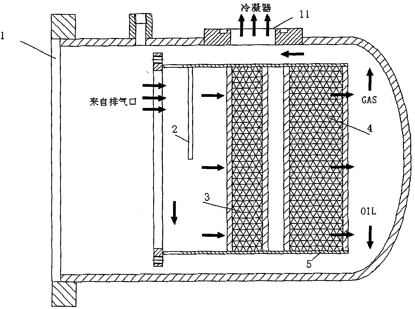
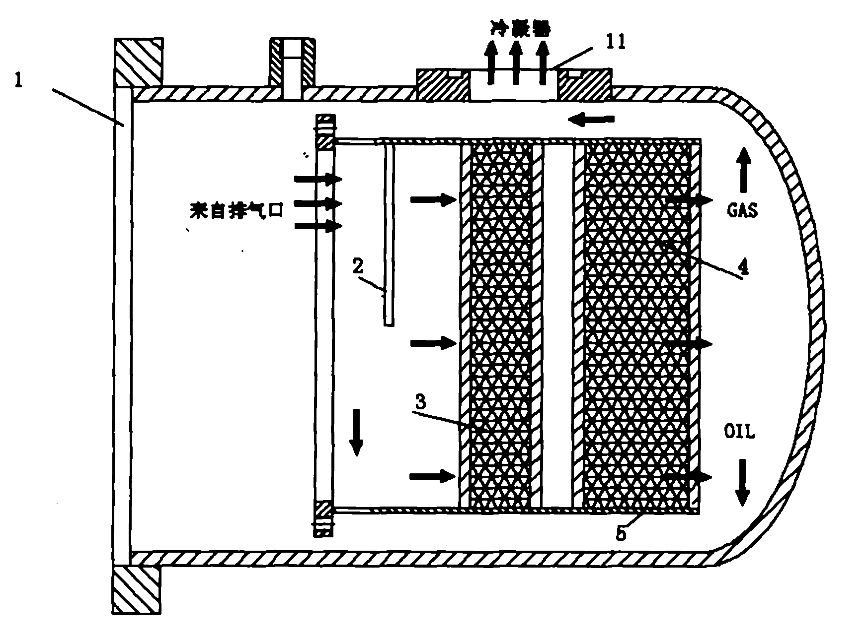
[0009] Depend on figure 1 Visible: the present invention comprises: oil separation shell 1; One side of described oil separation shell 1 has the hole 11 that joins with condenser; An oil drum 5 is fixedly placed in described oil separation shell 1; A baffle plate 2 is arranged at the front end of the barrel 5; one end of the baffle plate 2 is connected with the inner wall of the oil barrel 5, and the other end of the baffle plate 2 has a distance from the corresponding inner wall of the oil barrel 5; It is the first filter screen 3 connected to the inner wall of the oil barrel 5; the distance from the first filter screen 3 also includes the second filter screen 4 connected to the inner wall of the oil drum 5.

[0010] The oil separation casing in the present invention is at the outermost side of the whole structure, the oil barrel is inside the...


PUM


Abstract

The invention relates to an oil separator in a compressor. The oil separator comprises an oil separating shell; one side of the oil separating shell is provided with a hole which is connected with a condensor; and the oil separating shell is internally fixedly provided with an oil drum. The oil separator is characterized in that the front end of the oil drum is provided with a baffle plate; one end of the baffle plate is connected with the inner wall of the oil drum, and a distance is arranged between the other end of the baffle plate and the correspondng inner wall of the oil drum; the rear side of the baffle plate is provided with a first filter screen which is connected with the inner wall of the oil drum; and a second filter screen which is connected with the inner wall of the oil drum is arranged apart from the first filter screen. The invention has the beneficiall effects that the oil separator has higher oil separating efficiency than that of the traditional oil separation and secondary oil separation, and the lubricating oil carried by exhaust air can be effectively separated, thus the systematic design is simplified, and the cost is saved.

Description

technical field [0001] The invention relates to a compressor, in particular to an oil separation structure in the compressor. Background technique [0002] The oil separation effect in the prior art compressor is not ideal, and the customer needs to configure a secondary oil separation to ensure the oil separation effect, which makes the system more complicated and wastes cost. How to design an oil separation structure that simplifies system design and saves cost is a problem that technicians need to solve. Contents of the invention [0003] The technical problem to be solved by the present invention is to provide an oil separator in a compressor, aiming at solving the above problems. [0004] In order to solve the above technical problems, the present invention is achieved through the following technical solutions: [0005] The invention comprises: an oil separation shell; a hole connected to a condenser is opened on one side of the oil separation shell; an oil drum is ...

Claims


Application Information

Patent Timeline
Patent Type & Authority Applications(China)
IPC IPC(8): F04C29/02
Inventor 谢鹏
Owner SHANGHAI HANBELL PRECISE MASCH CO LTD
Why Eureka
Try Eureka