Waveform display method

A waveform display, waveform technology, applied in the direction of digital variable display, etc., can solve the problem of long waveform refresh display time and so on

Active Publication Date: 2011-07-06
RIGOL
View PDF6 Cites 27 Cited by
  • Summary
  • Abstract
  • Description
  • Claims
  • Application Information

AI Technical Summary

Problems solved by technology

[0017] In order to solve the problem that the waveform refresh display time is to

Method used


Image

  • Waveform display method
  • Waveform display method
  • Waveform display method

Examples


Embodiment Construction

[0037] The best implementation mode of the present invention will be introduced below in conjunction with the accompanying drawings.

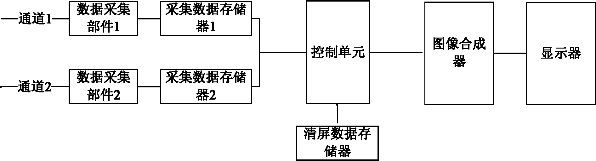
[0038] Such as image 3 As shown, in this embodiment, the dual-channel digital oscilloscope includes channel 1, channel 2, acquisition data memory 1, acquisition data memory 2, control unit, image synthesizer and display, and channel 1 and channel 2 are used to receive external input The measured signal is sent to the data acquisition part 1 and the data acquisition part 2. The data acquisition part includes an analog front-end part and an analog-to-digital conversion part for filtering, amplifying and analog-to-digital conversion of the measured signal, and then the The obtained digital signal is sent to the acquisition data memory 1 and the acquisition data memory 2 to obtain the waveform data for display, the control unit performs calculation processing on the waveform data according to various setting information of the instrument, and send...


PUM


Abstract

The invention provides a waveform display method, which is used for a digital oscilloscope to represent a stored waveform in the form of a displayed waveform on a display screen and which comprises the following steps of: 1) according to the display characteristics information and the waveform data of the displayed waveform, clearing the screen; and 2) according to the display characteristics information and the waveform data of the stored waveform, representing the displayed waveform on the display screen, and updating the display characteristics information and the waveform data of the displayed waveform. The waveform display method of the invention not only can greatly improve the refreshing display time of the waveform, but is also simple in implementation.

Description

technical field [0001] The invention relates to a waveform display method of a digital oscilloscope. Background technique [0002] A digital oscilloscope generally includes an analog front-end circuit, an analog-to-digital converter, a control processor, a graphics card, and a display screen that are connected in sequence. The analog front-end circuit is used to collect the measured signal and transmit it to the analog-to-digital converter. Convert the collected measured signal into a digital signal and send it to the control processor. The control processor is used to perform various digital processing on the digital signal, and present the processed result on the display screen of the digital oscilloscope in the form of a waveform. . [0003] In the prior art, digital oscilloscopes generally have the following processing methods when displaying waveforms, such as figure 1 Shown: [0004] 101: In the data collection step, the analog front-end circuit collects the measure...

Claims


Application Information

Patent Timeline
IPC IPC(8): G01R13/02
Inventor 王悦王铁军李维森
Owner RIGOL
Why Eureka
Try Eureka