Light guide board, backlight module and method for transmitting light

A technology of backlight module and light guide plate, which is applied in the field of light guide plate, can solve the problem of light L loss and achieve the effect of improving utilization efficiency

Inactive Publication Date: 2011-07-13
苏州向隆塑胶有限公司
View PDF0 Cites 28 Cited by
  • Summary
  • Abstract
  • Description
  • Claims
  • Application Information

AI Technical Summary

Problems solved by technology

However, the light guide plate 100a still has the following problem, that is, the light L will exit fro

Method used


Image

  • Light guide board, backlight module and method for transmitting light
  • Light guide board, backlight module and method for transmitting light
  • Light guide board, backlight module and method for transmitting light

Examples


Embodiment Construction

[0025] Below in conjunction with accompanying drawing and specific embodiment the present invention is described in further detail:

[0026] In view of this, the present invention provides a light guide plate with high light utilization efficiency.

[0027] The present invention provides a backlight module, which has the above-mentioned light guide plate and can provide a uniform surface light source.

[0028] The invention provides a method for conducting light, which can solve the problem of dark bands caused by the through holes in the light guide plate.

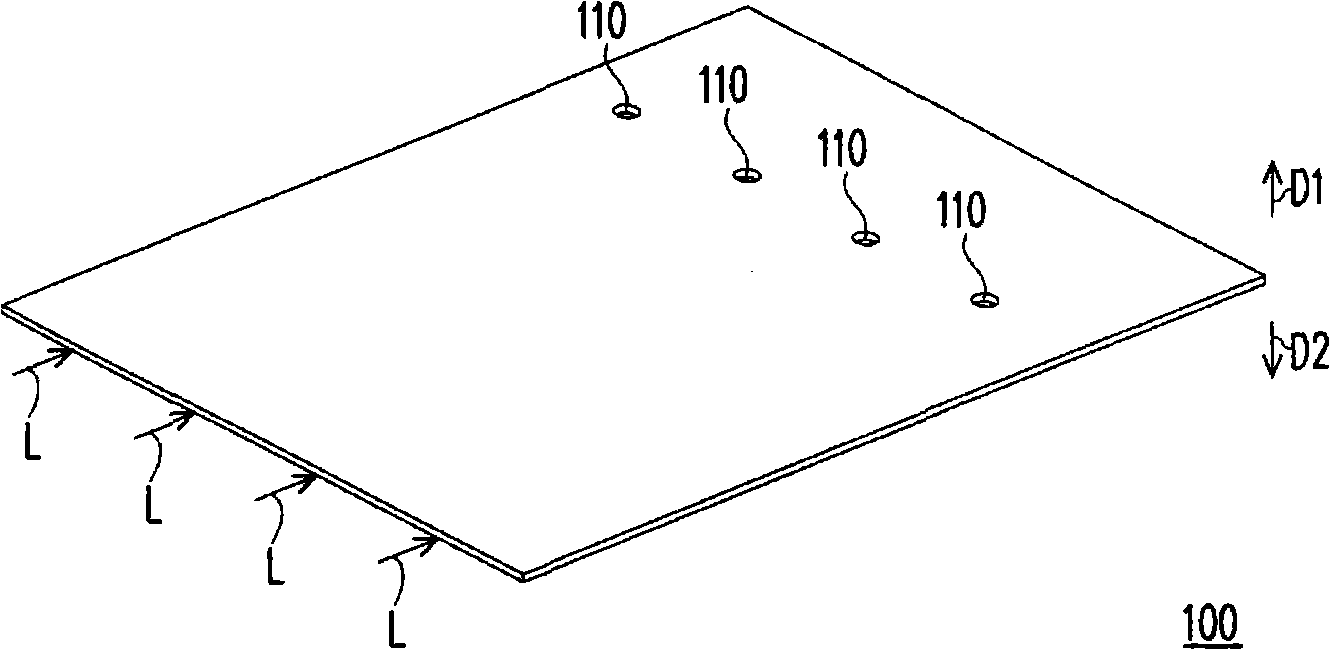
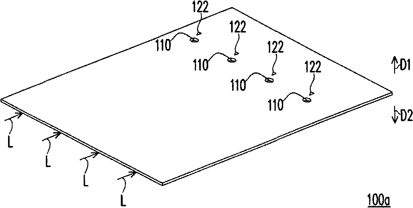
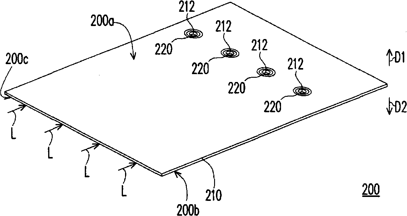
[0029] Based on the above, the present invention proposes a light guide plate. The light guide plate has a bottom surface, a light emitting surface opposite to the bottom surface, and a light incident surface connecting the bottom surface and the light emitting surface. Light can enter the light incident surface and be conducted in the light guide plate. The light guide plate includes: a light-transmitting substrate an...


PUM


Abstract

The invention relates to a light guide board, a backlight module and a method for transmitting light. The light guide board comprises a bottom surface, a light emergent surface opposite to the bottom and a light incident surface connected with the bottom surface and the light emergent surface, and light enters the light incident surface and is transmitted in the light guide board. The light guide board also comprises a light transmission substrate and a first groove, wherein the light transmission substrate is provided with at least one through hole, the first groove is arranged on the light transmission substrate and on the periphery of the through holes. The invention can solve the problem of dark zone behind the through hole and can improve the utilization efficiency of the light.

Description

technical field [0001] The invention relates to a backlight module, in particular to a light guide plate in the backlight module. Background technique [0002] Light guide plates are used in backlight modules such as side-illuminated liquid crystal displays and lighting equipment. In recent years, light guide plates have been used in various electronic devices to introduce design elements such as color and light into the appearance of the electronic devices. [0003] figure 1 It is a three-dimensional schematic diagram of a light guide plate in the prior art. exist figure 1 The first direction D1 and the second direction D2 are marked in , wherein the first direction D1 can be understood as the rear (lower side) of the light guide plate 100 , and the second direction D2 can be understood as the front (upper side) of the light guide plate 100 . A through hole 110 is usually provided at a position of the light guide plate 100 corresponding to a component (not shown) of the...

Claims


Application Information

Patent Timeline
IPC IPC(8): F21V8/00F21V7/04G02F1/13357
Inventor 林育政邱冠凯李信坤
Owner 苏州向隆塑胶有限公司
Why Eureka
Try Eureka