Method and system for allocating discrete resources
A resource allocation and resource technology, applied in the field of communication, can solve the problem of large system overhead of resource allocation signaling format, etc., and achieve the effect of realizing overhead and flexibility, low overhead, and easy implementation
- Summary
- Abstract
- Description
- Claims
- Application Information
AI Technical Summary
Problems solved by technology
Method used
Image
Examples
Embodiment
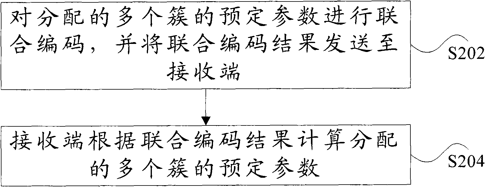
[0053] In this embodiment, the number of clusters allocated to a discrete resource is equal to 2 as an example, combined with Figure 3 to Figure 5 The above discrete resource allocation method is described in detail. Assuming that there are N resource blocks that can be allocated, the method includes the following steps:
[0054] Step 1, the system (specifically, it can be a base station) is configured with 4 coprime numbers, set as m 1 , m 2 , m 3 , m 4 . In this example, D 1 = 0; D 2 = 0; D 3 = 0; D 4 = 0, then [0, m 1 ) represents the dynamic range of the starting point of cluster 1; [1, m 2 ] represents the dynamic range of the length of cluster 1; [0, m 3 ) represents the dynamic range of the starting point of cluster 2; [1, m 4 ] represents the dynamic range of the length of cluster 2.
[0055] Step 2, assuming that in a certain resource allocation, the starting point of allocated cluster 1 is x 1 ,D 1 ≤x 1 1 +D 1 , with length L 1 ,D 2 ≤ L 1 -12 +D ...
example 1
[0071] In this example, suppose D 1 = 0; D 2 = 0; D 3 = 0; D 4 =0, system bandwidth=25RB, the number of RBs available for resource allocation is also 25, and the minimum unit of resource allocation in this example is RB. The starting point of the resource allocation of the two clusters adopts the following method, that is, the starting point x of cluster 1 1 The corresponding resource block index is x 1 , the starting point x of cluster 2 2 The corresponding resource block index is N-1-x 2 , further m 1 , m 2 , m 3 , m 4 The value is: m 1 =14,m 2 =9,m 3 =13,m 4 =5, at this time the resource allocation of the two clusters satisfies the following relationship:
[0072] The first RB index of cluster 1 ranges from [RB 0 to RB 13]; the number of RBGs allowed to be allocated in cluster 1 can be 1 to 9;
[0073] The first RB index range of cluster 2 is [RB12~RB24], and the number of RBGs allowed to be allocated by cluster 2 can be 1~5.
[0074] Assuming that the two c...
example 2
[0081] In this example, suppose D 1 = 0; D 2 = 0; D 3 = 0; D 4 = 0, system bandwidth = 50 RB, according to the existing standard, the number of RBGs available for resource allocation is 17, and the smallest unit of resource allocation in this example is RBG. The starting point of the resource allocation of the two clusters adopts the following method, that is, the starting point x of cluster 1 1 The corresponding resource block index is x 1 , the starting point x of cluster 2 2 The corresponding resource block index is x 2 , further m 1 , m 2 , m 3 , m 4 The value is: m 1 =19,m 2 = 3, m 3 =17,m 4 = 2, at this time the resource allocation of the two clusters satisfies the following relationship:
[0082] The range of the first RB index of cluster 1 is [RBG0~RBG16]; the number of RBs allowed to be allocated in cluster 1 can be 1~3;
[0083] The first RB index range of cluster 2 is [RBG0~RBG16], and the number of RBs allowed to be allocated by cluster 2 can be 1~2....
PUM
 Abstract
Description
Claims
Application Information
 - R&D
- Intellectual Property
- Life Sciences
- Materials
- Tech Scout
- Unparalleled Data Quality
- Higher Quality Content
- 60% Fewer Hallucinations
Browse by: Latest US Patents, China's latest patents, Technical Efficacy Thesaurus, Application Domain, Technology Topic, Popular Technical Reports.
© 2025 PatSnap. All rights reserved.Legal|Privacy policy|Modern Slavery Act Transparency Statement|Sitemap|About US| Contact US: help@patsnap.com


