Two-dimensional coding method

a coding method and holography technology, applied in the field of two-dimensional coding methods for holography, can solve the problems of difficult to set an absolute threshold value, difficulty in maintaining the intensity of diffracted light, and the difficulty of conventional differential coding methods, etc., and achieve the effect of simplifying the decoding processing

Inactive Publication Date: 2010-09-21
FUJIFILM BUSINESS INNOVATION CORP
View PDF13 Cites 0 Cited by
  • Summary
  • Abstract
  • Description
  • Claims
  • Application Information

AI Technical Summary

Benefits of technology

[0012]The present invention has been achieved in views of the above and provides a two-dimensional coding method for holography capable of recording and reproducing a large amount of data with a small number of pixels without any complicated decoding process.
[0017]The present invention has such an effect that decoding processing is simplified so that a larger number of data can be recorded and reproduced with a smaller number of pixels.

Problems solved by technology

However, it is difficult to set an absolute threshold value because the intensity of diffracted light is difficult to be maintained at a constant level.
However, a conventional differential coding method has various problems.
For example, a generalized differential coding method has such a problem that data amount per page is small because it allows expression of 1-bit with a single data pixel.
In the gray scale differential coding method, calculation for detecting the brightness of reproduced pixel is complicated, and additional calculation is required for decoding to original binary data using that brightness.
Therefore, there is a problem that decoding process is so complicated that reproduction takes a long time.

Method used


Image

  • Two-dimensional coding method
  • Two-dimensional coding method
  • Two-dimensional coding method

Examples


Embodiment Construction

[0030]Hereinafter an example of the embodiment of the present invention will be described in detail with reference to the accompanying drawings.

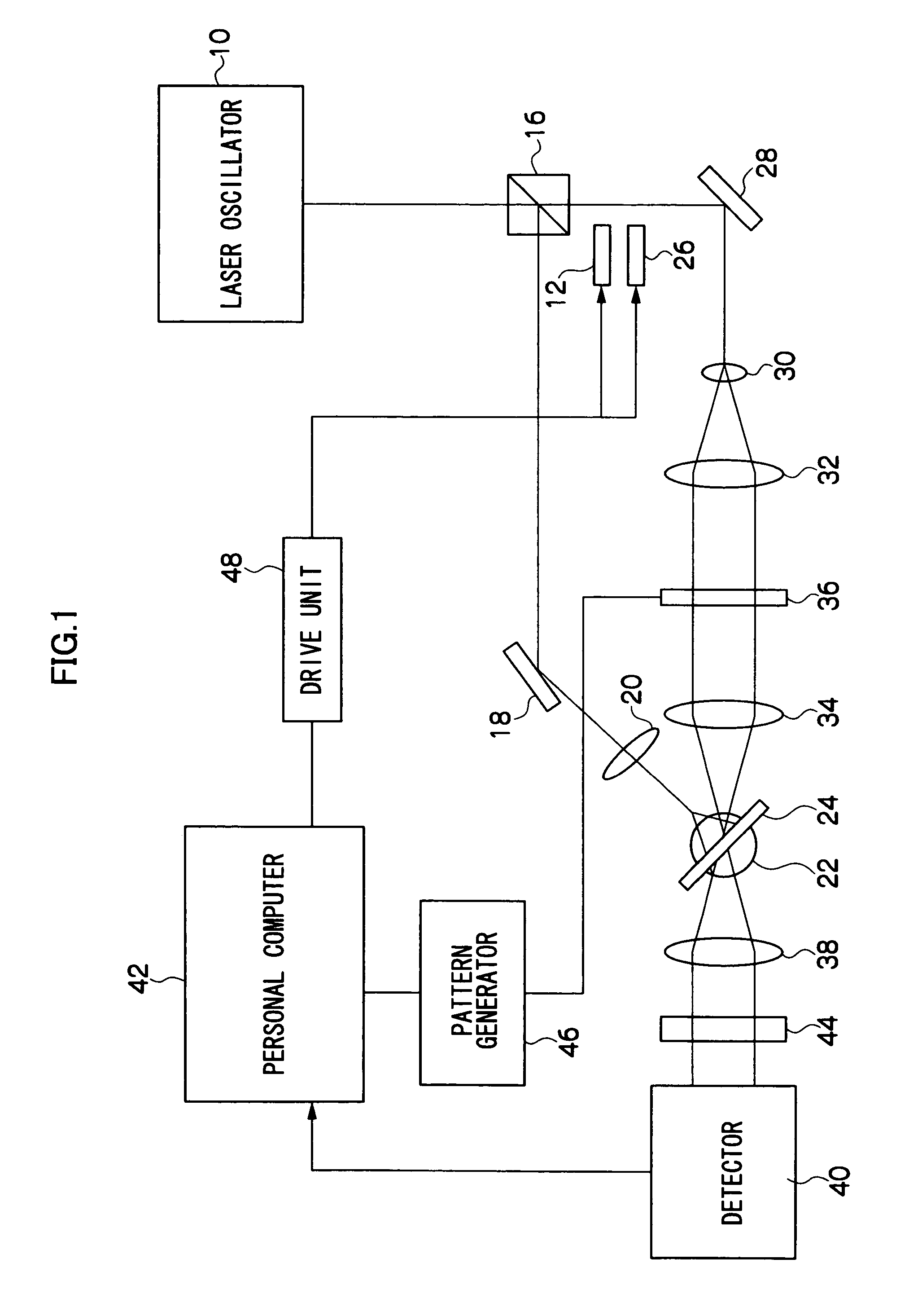
[0031]FIG. 1 is a schematic diagram showing the structure of a hologram recording / reproducing apparatus.

[0032]As shown in FIG. 1, this hologram recording / reproducing apparatus is provided with a laser oscillator 10 using, for example, Nd:YVO4 crystal. Laser beam having a wavelength of 532 nm, which is coherent light, is oscillated and irradiated from the laser oscillator 10. A polarization beam splitter 16 for separating laser beam to light for reference light and light for signal light by transmitting P polarized beam while reflecting S polarized beam is provided on the laser beam irradiation side of the laser oscillator 10.

[0033]A reflection mirror 18 for changing light passage in a direction to a hologram recording medium by reflecting laser beam for reference light and an objective lens 20 for generating reference light composed of spher...


PUM


Abstract

A two-dimensional coding method includes: using a two-dimensional image containing plural reference pixels each having a different brightness and data pixels representing data in accordance with brightness; and coding a binary sequence of plural bits to be recorded as a hologram by matching the brightness level of the data pixel based on the brightnesses of the plural reference pixels.

Description

CROSS-REFERENCE TO RELATED APPLICATION[0001]This application claims priority under 35 USC 119 from Japanese Patent Application No. 2005-272909, the disclosure of which is incorporated by reference herein.BACKGROUND OF THE INVENTION[0002]1. Field of the Invention[0003]The present invention relates to a two-dimensional coding method for holography and more particularly to a two-dimensional coding method for coding binary sequence in correspondence with brightness level of a pixel of a two-dimensional image.[0004]2. Description of the Related Art[0005]In holography technology, signal light and reference light are irradiated to a recording medium, and diffraction grating is formed based on an interference pattern in a recording medium to record a hologram. Then, by irradiating reference light to a recorded hologram, the signal light is reproduced due to diffraction by the hologram. That is, diffracted light from the hologram has the same wave front as the signal light.[0006]The signal l...

Claims


Application Information

Patent Timeline
Patent Type & Authority Patents(United States)
IPC IPC(8): G06K9/36G03H1/00
CPCG11B7/0065G11B7/00781G11B20/10G11B2220/2504
Inventor YASUDA, SHINMINABE, JIROKAWANO, KATSUNORIOGASAWARA, YASUHIROHAYASHI, KAZUHIROYOSHIZAWA, HISAEHAGA, KOICHIFURUKI, MAKOTO
Owner FUJIFILM BUSINESS INNOVATION CORP
Why Eureka
Try Eureka