Hydraulic aggregate for underground transportation vehicle

A technology for hydraulic units and transportation tools, which can be used in fluid pressure actuation system components, mechanical equipment, fluid pressure actuation devices, etc., and can solve problems such as limitations.

Active Publication Date: 2011-07-20
JUNGHEINRICH AG
View PDF9 Cites 8 Cited by
  • Summary
  • Abstract
  • Description
  • Claims
  • Application Information

AI Technical Summary

Problems solved by technology

Possibilities of forming recesses in the tank are significantly limited in this method

Method used


Image

  • Hydraulic aggregate for underground transportation vehicle
  • Hydraulic aggregate for underground transportation vehicle
  • Hydraulic aggregate for underground transportation vehicle

Examples


Embodiment Construction

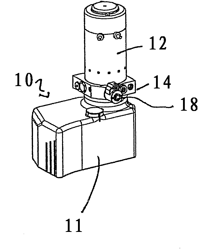
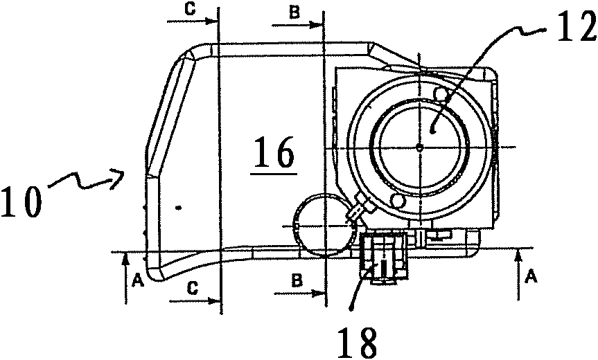
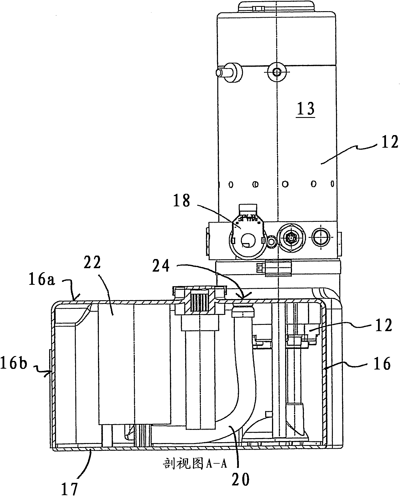
[0029] figure 1 and 2 A compact hydraulic unit 10 is shown with an installed motor-pump unit 12 and a tank 11 . The tank 11 is composed of a tank body 16 and a tank cover 17 . The tank shell 16 has an upper side 16 a and a surrounding side wall 16 b which is laser welded to the substantially planar tank cover 17 . This weld is welded on the end face of the side wall 16b facing away from the upper side 16a to the surface of the tank top plate 17 pointing inwards towards the tank interior. If the welding is done at the contact surface between the tank cover and the tank shell, the laser thus only follows the two-dimensional contour of the tank circumference and no height adjustment is necessary.

[0030] Mounted on the motor-pump unit 12 is a valve housing 14 which has a solenoid valve 18 . With the hydraulic unit 10 shown, for example, lift cylinders (not shown) in a ground vehicle can be actuated. When the motor 13 in the motor-pump unit 12 is switched on, hydraulic mediu...


PUM


Abstract

The present invention relates to a hydraulic aggregate for an underground transportation vehicle, which comprises the following components: a tank which comprises a tank shell and a tank shroud that are respectively made of plastic; a motor pump unit which is provided on the tank; a reflux filter unit which comprises a filter housing that is made of plastic and a filter element that is provided in the filter housing, wherein the reflux unit is provided with a hose joint and a discharge outlet, and the filter unit is provided in a flow path between the hose joint and the discharge outlet; and a reflux hose which connects the motor pump unit with the hose joint, wherein the filter housing is integrated with the tank housing or the tank shroud, and the tank shell and the tank shroud are welded with each other.

Description

technical field [0001] The invention relates to a ground transportation vehicle hydraulic unit. Background technique [0002] For lifting and lowering loads, ground vehicles are equipped with hydraulic units. A hydraulic unit usually consists of a drive motor (mostly an electric motor) and a pump driven by the drive motor. To lift the load, for example a single-acting lifting cylinder is actuated via a hydraulic unit, wherein a non-return valve can be provided in the hydraulic unit for load retention on the hydraulic unit. If the lowering is effected by means of a ground vehicle, the hydraulic medium flows back into the hydraulic unit via the return line. [0003] In hydraulic assemblies, it is known to assemble motors, pumps and valve arrangements as a unit in a common housing and to connect this housing as a motor-pump unit to a hydraulic tank from which the pump sucks in hydraulic medium. It is also known that the return hydraulic medium is not directed into the tank...

Claims


Application Information

Patent Timeline
Patent Type & Authority Applications(China)
IPC IPC(8): B66F9/22F15B21/00
CPCB66F9/22
Inventor D・威尔斯S・霍纳
Owner JUNGHEINRICH AG
Why Eureka
Try Eureka