Transmission device

A kind of transmission device and active technology, which is applied in the direction of transmission device, transmission device parts, friction transmission device, etc., can solve the problems of increasing energy consumption and complex structure, and achieve the effect of reducing energy consumption and simplifying power configuration

Active Publication Date: 2013-12-04
CHINA SHENHUA ENERGY CO LTD +1
View PDF5 Cites 0 Cited by
  • Summary
  • Abstract
  • Description
  • Claims
  • Application Information

AI Technical Summary

Problems solved by technology

In this way, two sets of driving mechanisms are required to realize the final rotary motion of the actuator, which increases energy consumption and makes the structure very complicated

Method used


Image

  • Transmission device
  • Transmission device
  • Transmission device

Examples


Embodiment approach

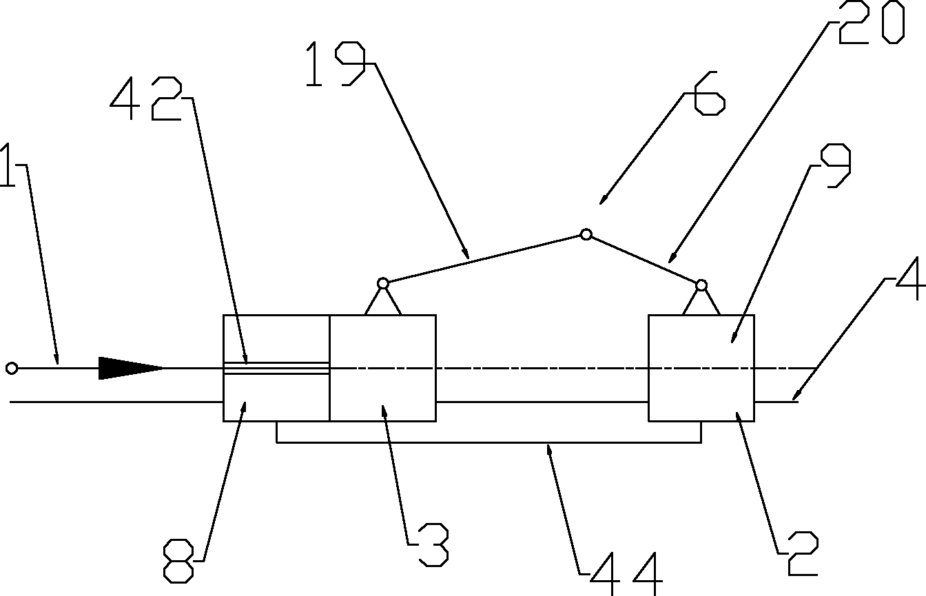
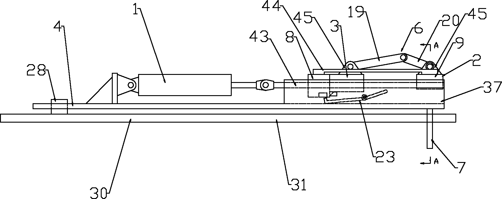
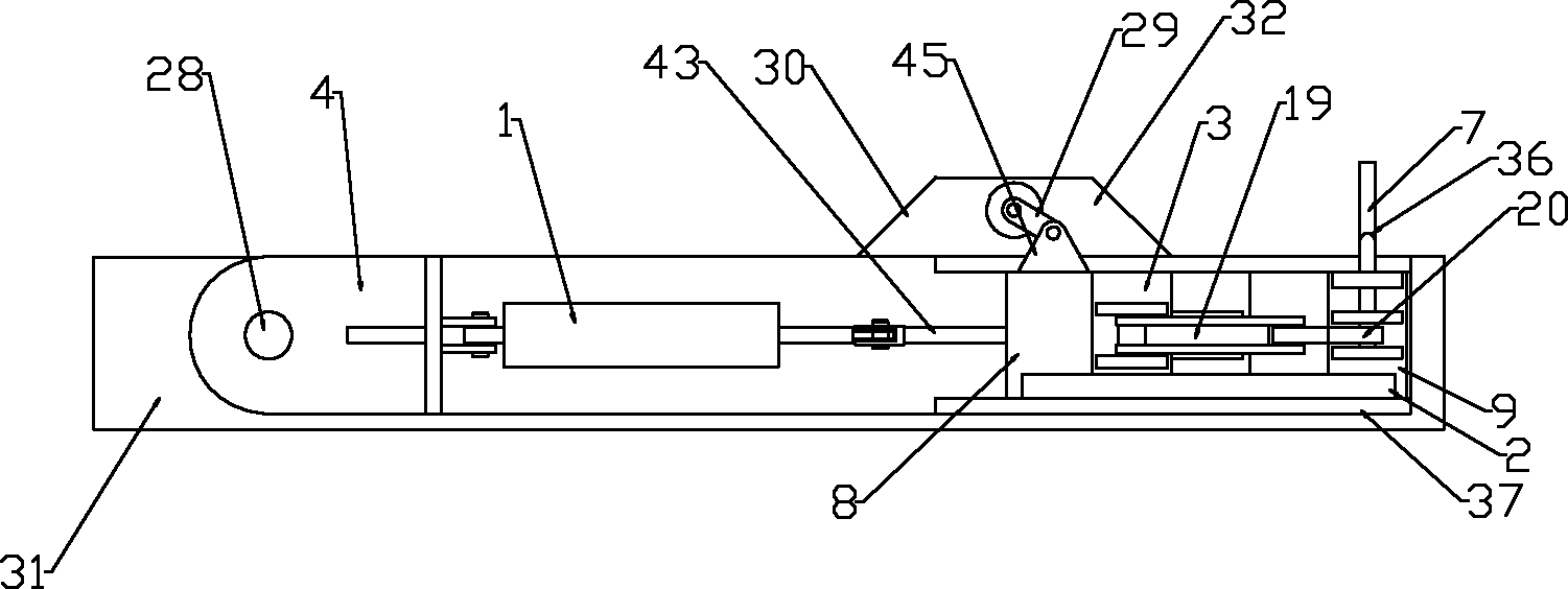
[0067] The passive slider 2 may have only one slider or two or more sliders. In order to facilitate the connection and release between the passive slider 2 and the active slider 3, according to a preferred implementation of the present invention In this way, the passive slider 2 includes a first slider 8 and a second slider 9. The first slider 8 and the second slider 9 are fixedly connected and spaced apart, and the active slider 3 is located in the first slider. Between the sliding block 8 and the second sliding block 9, the first sliding block 8 is pivotally connected to the side portion 32 through the first connecting rod 29. The first sliding block 8 and the second sliding block 9 may be fixedly connected by various suitable methods, for example, fixedly connected by a connecting rod 44. Specifically, one end of the connecting rod 44 is fixedly connected to the first sliding block 8 (for example, by welding or fastening connection), and the other end of the connecting rod 4...


PUM


Abstract

The invention provides a transmission device which comprises a guide rail (4), a driving slide block (3), a driven slide block (2), a locking mechanism (5) and a motion switching mechanism (6), wherein the driving slide block and the driven slide block can be slidably arranged on the guide rail; the locking mechanism has a locking state and a releasing state; when in the locking state, the locking mechanism locks the driven slide block to the driving slide block so as to drive the driven slide block to perform linear movement, and when in the releasing state, the locking mechanism releases the locking between the driving slide block and the driven slide block; and the motion switching mechanism is installed on the driving slide block and the driven slide block, and is used for converting the linear motion of the driving slide block to the rotation movement when in the releasing state. Linear reciprocating motion and rotation motion can be realized sequentially by the transmission device through utilizing a linear motion driving mechanism, and finally rotation movement can be carried out through driving executive elements, thus the energy consumption is reduced, and the motive configuration is simplified.

Description

Technical field [0001] The invention relates to a transmission device. Background technique [0002] The existing driving mechanism usually only realizes one kind of movement. For example, the hydraulic cylinder can realize the linear reciprocating movement, and the motor can realize the rotary movement. Due to the limitations of the existing drive mechanism, it is impossible to use a set of drive mechanism to simultaneously realize linear reciprocating motion and rotary motion. In some applications, a set of linear motion drive mechanism may be required to drive the rotary motion drive mechanism to a certain position, and then use the rotary motion drive mechanism to drive the actuator to perform rotary motion. In this way, two sets of driving mechanisms are needed to realize the final rotational movement of the actuator, thereby increasing energy consumption and making the structure very complicated. Summary of the invention [0003] The purpose of the present invention is to ...

Claims


Application Information

Patent Timeline
Patent Type & Authority Patents(China)
IPC IPC(8): F16H57/00F16H21/16F16H19/04F16B1/04
Inventor 陈冰
Owner CHINA SHENHUA ENERGY CO LTD
Why Eureka
Try Eureka