LED (light-emitting diode) daylight lamp

A technology of LED fluorescent lamp and lamp body, which is applied in the field of lamps and lanterns, can solve the problems of inability to adapt to adjustment requirements, laborious operation, complex adjustment structure, etc., and achieve the effect of avoiding electrode lead wires from being knotted or torn off, convenient and fast positioning, and reliable positioning

Active Publication Date: 2012-08-22
SELF ELECTRONICS CO LTD
View PDF8 Cites 0 Cited by
  • Summary
  • Abstract
  • Description
  • Claims
  • Application Information

AI Technical Summary

Problems solved by technology

LED light sources have many advantages such as energy saving, environmental protection, and long service life. People began to replace fluorescent lamps with LED light sources. The room is a fixed connection structure, which cannot meet the adjustment requirements for different lighting directions.
[0003] In the prior art, in order to solve the problem that the light direction of the LED lamp tube cannot be adjusted, for example, the utility model "A LED Fluorescent Tube with a Rotatable Lamp Head" with the patent No. ZL200920192636.5 discloses a LED fluorescent lamp with a rotatable lamp head. It includes an LED light source and a radiator. The LED light source is fixed on the radiator through the base plate. There are lamp caps at both ends of the radiator. Pins are arranged on the lamp caps. A stator and a rotor are arranged between the lamp cap and the radiator. The stator is fixed on the radiator. , the lamp head is fixed on the rotor, the rotor is installed on the stator, and the rotation limiting mechanism and the elastic positioning mechanism are respectively arranged between the stator and the rotor
Although the above-mentioned patent can realize the adjustment of the illumination angle of the LED lamp tube, the adjustment structure of this patent is relatively complicated. In addition to the rotating mechanism (including the stator and the rotor), there is also an elastic positioning structure that limits the rotation of the rotating mechanism. The rotor is inside the stator. After a certain range of rotation, the rotor is fixed in the stator through an elastic positioning mechanism. During operation, an external force must be applied to ensure the rotation of the rotor relative to the stator, which is laborious to operate; moreover, the lamp cap of the patented LED lamp still uses The pin structure realizes the electrical conduction with the lamp holder. After using for a certain period of time, due to the wear or failure of the spring of the elastic positioning structure, the positioning column in the stator may not be able to fall into the positioning slot in the rotor. At this time, even if The LED lamp tube is rotated to a suitable lighting angle, and the reliable connection between the lamp head and the lamp holder of the lamp tube cannot be guaranteed.

Method used


Image

  • LED (light-emitting diode) daylight lamp
  • LED (light-emitting diode) daylight lamp
  • LED (light-emitting diode) daylight lamp

Examples


Embodiment Construction

[0022] The present invention will be described in further detail below in conjunction with the embodiments of the drawings.

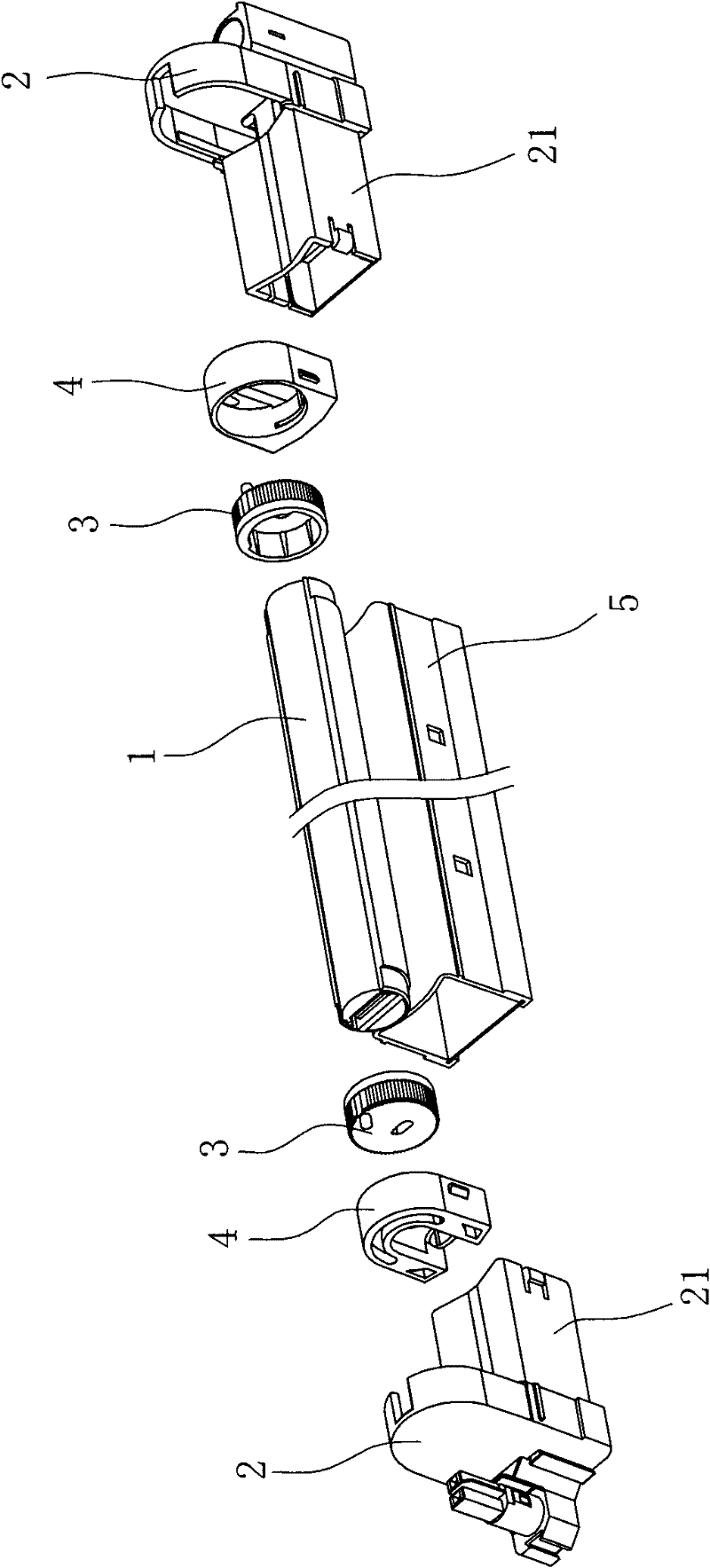
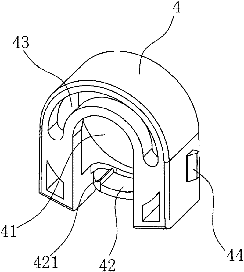
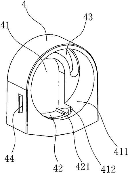
[0023] Such as Figure 1~Figure 10 Shown is a specific embodiment of the present invention. This embodiment is an LED fluorescent lamp, which includes a lamp body 1, a lamp holder arranged at both ends of the lamp body 1, and a lamp holder 2 connected to each lamp holder, wherein each The lamp holder includes a mutually rotatable end cover 3 and a fixing base 4. The end cover 3 is fixedly connected to the end of the lamp body 1, and the fixing base 4 is fixedly arranged in the corresponding lamp socket 2 between the two lamp sockets 2. A base 5 with the same length as the lamp body 1 is also provided. The base 5 is used for the installation and connection parts of the overall LED fluorescent lamp, and can also support the lamp body 1 and improve the reliability of the connection of the lamp body 1; A power circuit board is provided, a U-shaped groove is op...


PUM


Abstract

The invention relates to an LED (light-emitting diode) which comprises a lamp body, a lamp head and a lamp connecting socket. The daylight lamp is characterized in that the lamp head comprises an end cover and a fixed seat; the end cover is provided with a thread hole; the end surface of the end cover is provided with a limiting column; the outer peripheral surface of the end cover is provided with a tooth groove; the fixed seat is provided with a hole cavity; the end cover is contained in the hole cavity and rotates relatively; a limiting groove is molded on one end surface of the hole cavity of the fixed seat; the limiting column penetrates through the limiting groove and is limited at two ends of the limiting groove; an elastic plate is molded at the inner side surface of the hole cavity; one end of the elastic plate and the inner side surface of the hole cavity are connected into a whole; and the free end of the elastic plate is provided with a raised line which can be matched with the tooth groove. According to the invention, the lamp body can be fixed at the position after rotating for any angle relatively to the fixed seat, and the reliable positioning at the direction of illumination of the lamp body is ensured; and because of the rotation limiting effect of the limiting groove, the lamp body only can rotate within the range of 180 degrees, the lamp body is avoided from rotating within the range of 360 degrees randomly, thus preventing an electrode lead wire from being knotted or broken due to the lamp body rotates for an oversize angle.

Description

Technical field [0001] The invention relates to a lamp, especially an LED fluorescent lamp. Background technique [0002] Traditional fluorescent lamps are illuminated by fluorescent lamps. The fluorescent tube can emit light in a circle along the outer circumference of the tube. Moreover, the fluorescent tube and the lamp holder are usually fixedly connected. When the fluorescent lamp is installed on the lamp holder, the pins on the lamp holder are required. Insert into the socket in the lamp holder to realize electrical connection. LED light source has many advantages such as energy saving, environmental protection and long service life. People began to use LED light source to replace fluorescent lamp, but the light source part of LED tube is mostly flat, which can only emit light in one direction, while traditional lamp holder and lamp holder It is a fixed connection structure, which cannot adapt to the adjustment requirements of different light directions. [0003] In the pri...

Claims


Application Information

Patent Timeline
Patent Type & Authority Patents(China)
IPC IPC(8): F21S2/00F21V17/10F21V19/02F21V15/00F21V5/04F21Y101/02
CPCF21V19/008F21S8/031F21Y2101/02F21Y2115/10
Inventor 季丰郑兆勇林万炯
Owner SELF ELECTRONICS CO LTD
Why Eureka
Try Eureka