Electro-oculogram signal-based computer input control method

A technology of oculoelectric signal and control method, which is applied in the field of bioinformatics, and can solve problems such as inability to use computer input control, single control function, etc.

Inactive Publication Date: 2011-07-20
UNIV OF ELECTRONIC SCI & TECH OF CHINA
View PDF6 Cites 20 Cited by
  • Summary
  • Abstract
  • Description
  • Claims
  • Application Information

AI Technical Summary

Problems solved by technology

For example, the Chinese invention patent application with the publication number CN1601445A disclosed a "multifunctional human body bio-oculoelectric switch control device" on March 30, 2005, which includes an oculoelectric signal acquisition device, a single-chip embedded microcontroller processing, The switch drive circuit, etc., i

Method used


Image

  • Electro-oculogram signal-based computer input control method
  • Electro-oculogram signal-based computer input control method
  • Electro-oculogram signal-based computer input control method

Examples


Embodiment 1

[0024] Example 1: as Figure 5 As shown, a computer input control method based on eye electrical signals, comprising the following steps:

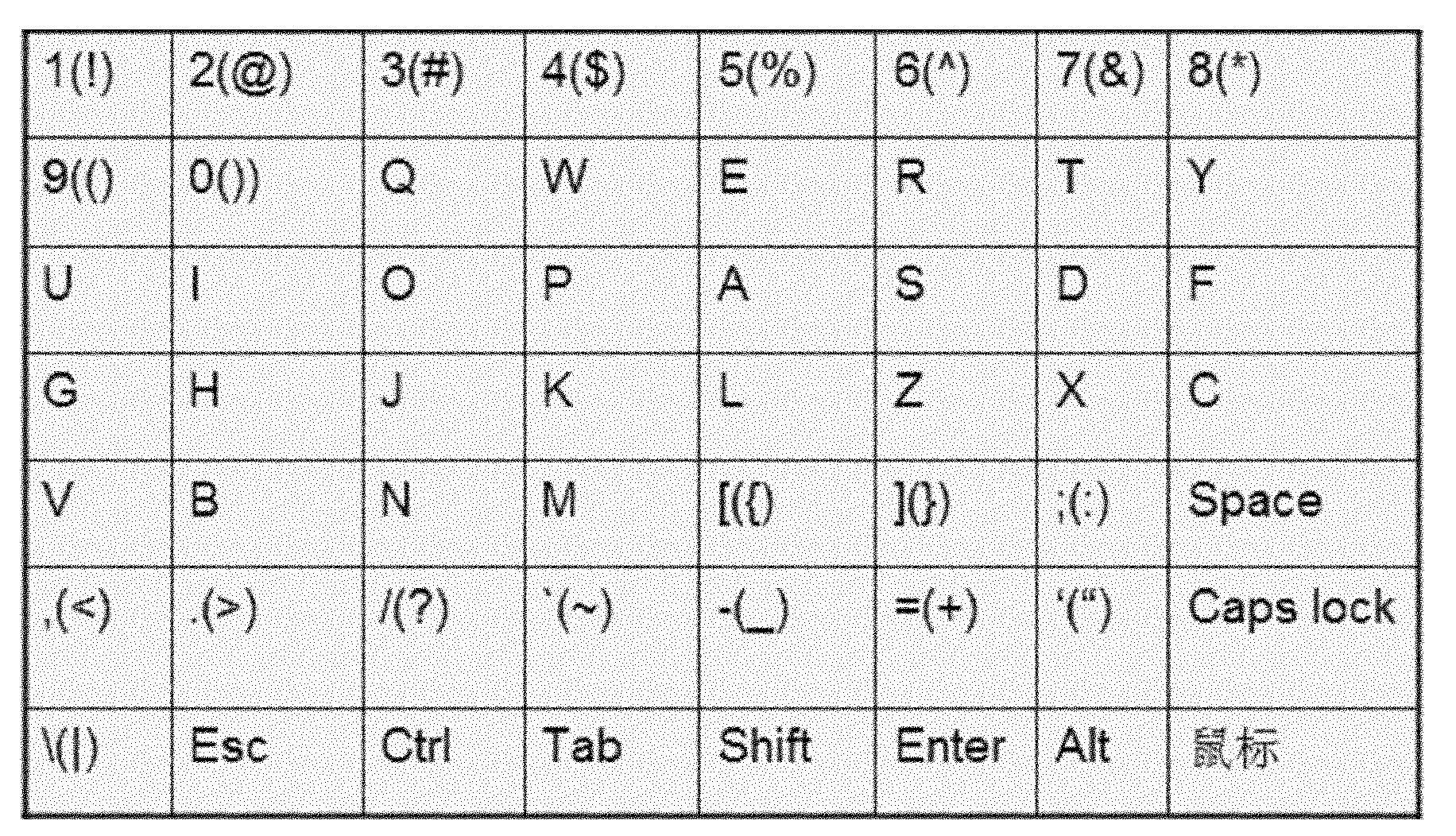
[0025] Step 1: A keyboard key selection area is preset in the computer, and the keys in the keyboard key selection area are arranged in a matrix with multiple rows and multiple columns.

[0026] The keyboard key selection area is as follows image 3 As shown, it consists of a matrix of M (such as M=8) columns × N rows (such as N=7), each matrix unit represents a keyboard key symbol, the symbol in the brackets of the keyboard key is to select "shift" first, The symbols output by the selected key to the computer, the non-displayed symbols Shift, Space, Caps lock, Esc, Ctrl, Alt, Tab and Enter in the keyboard selection area are defined in the same way as the general keyboard definitions.

[0027] Step 2: The key selection area of ​​the keyboard performs the switching of the highlighted selection area in a row-by-row cycle, the eye-electrici...

Embodiment 2

[0042] Example 2: as Image 6 As shown, a computer input control method based on eye electrical signals, comprising the following steps:

[0043] A computer input control method based on eye electrical signals, comprising the following steps:

[0044] Step 1: pre-set a mouse button selection area in the computer, and the buttons in the mouse button selection area are arranged in one row and multiple columns; the mouse button selection and mouse direction control area are as follows: Figure 4 As shown, it consists of a matrix of M (eg, M=11) columns×N rows (eg, N=1), and each matrix unit represents a mouse control command. "←" represents moving the mouse one horizontal step to the left (the horizontal step is 1 / 25 of the effective horizontal display distance of the computer monitor); "→" represents moving the mouse one horizontal step to the right; "↑" represents Move the mouse up by one vertical step (the vertical step is one-tenth of the effective vertical display distance...


PUM


Abstract

The invention relates to an electro-oculogram signal-based computer input control method which comprises the following steps of: 1, presetting a keyboard key selection area in a computer, wherein keys in the keyboard key selection area are arranged in a multi-row multi-column matrix; 2, circularly switching highlight selection area in the keyboard key selection area according to rows, acquiring and identifying an electro-oculogram and inputting the electro-oculogram serving as a control signal to the computer by an electro-oculogram acquisition transmission module, simultaneously stopping switching the highlight selection area according to the rows, and circularly switching highlight keys in the highlight selection area according to columns; and 3, acquiring and identifying the electro-oculogram again and inputting the electro-oculogram serving as the control signal to the computer by the electro-oculogram acquisition transmission module, and simultaneously stopping switching the highlight keys according to columns, wherein the highlight keys are used as the input control result of the computer. The method has the advantages that complex computer input control can be performed, and a user can use the computer without obstacles by using the method.

Description

technical field [0001] The present invention relates to the technical field of biological information, in particular to the control technology of oculoelectric signals. Background technique [0002] At present, the human-computer interaction system constructed by using the biological signals of the human body to communicate systematically with the computer or control equipment is the frontier and hotspot of the research on assistive devices for the disabled. For example, the Chinese invention patent application with the publication number CN1423228A, on June 11, 2003, disclosed a "device and method for recognizing the gaze direction of human eyes and its application", which includes a camera, an image interface and a hardware composed of a processor. Equipment, timed cycle image acquisition and human eye gaze direction recognition and non-contact intelligent control technology that uses human eye gaze as control instructions and auxiliary signals. For example, the blinking ...

Claims


Application Information

Patent Timeline
IPC IPC(8): G06F3/033G06F3/02G06F3/01
Inventor 刘铁军冯阳尧德中
Owner UNIV OF ELECTRONIC SCI & TECH OF CHINA
Why Eureka
Try Eureka