Synchronous injection decoding method and system for RFID system

A decoding method and a technology of a decoding unit, which are applied to cooperative devices, instruments, computer components, etc., can solve problems such as counting decoding errors and decoding data errors, and achieve the effect of avoiding clock drift

Active Publication Date: 2013-04-24
中国电子技术标准化研究所 +1
View PDF0 Cites 0 Cited by
  • Summary
  • Abstract
  • Description
  • Claims
  • Application Information

AI Technical Summary

Problems solved by technology

However, since mmc encoding is of equal data length, if the counting decoding method is used, decoding errors may be caused by counting deviations or clock offsets, resulting in errors in the final decoded data

Method used


Image

  • Synchronous injection decoding method and system for RFID system
  • Synchronous injection decoding method and system for RFID system
  • Synchronous injection decoding method and system for RFID system

Examples


Embodiment Construction

[0023] The following will clearly and completely describe the technical solutions in the embodiments of the present invention with reference to the accompanying drawings in the embodiments of the present invention. Obviously, the described embodiments are only some, not all, embodiments of the present invention. Based on the embodiments of the present invention, all other embodiments obtained by persons of ordinary skill in the art without creative efforts fall within the protection scope of the present invention.

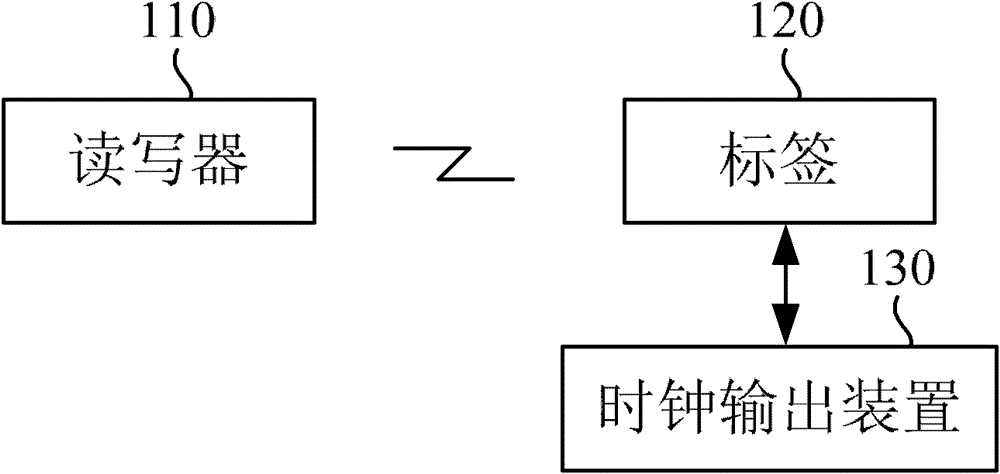
[0024] Such as figure 1 Shown is a schematic structural diagram of a synchronous injection decoding system for an RFID system provided by an embodiment of the present invention. The system includes: a reader-writer 110, a tag 120 and a clock output device 130, wherein the reader-writer 110 and the tag 120 The communication between them is carried out through radio frequency, and the tag 120 is connected with the clock output device 130 .

[0025] In this example, ...


PUM


Abstract

The embodiment of the invention provides a synchronous injection decoding method and a synchronous injection decoding system for an RFID (Radio Frequency Identification) system, wherein the method comprises the steps of: receiving mmc-encoded input data; taking the jumping of the input data as an enabling signal of a clock output data along a generated pulse signal in order to generate a clock signal clk with variable duty ratio and invariable cycle; and performing sampling decoding on the input data by using the clock signal generated by the clock output device. In the embodiment of the invention, stable synchronous clock signal is obtained based on phase locking method and decoding is implemented in accordance with the clock signal, thereby effectively avoiding erroneous mmc decoding derived from clock shift.

Description

technical field [0001] The invention relates to the field of radio frequency technology, in particular to a synchronous injection decoding method and system for RFID systems. Background technique [0002] Radio Frequency Identification (RFID) is a non-contact automatic identification technology. It automatically identifies the target object and obtains relevant data through radio frequency signals. The identification work does not require manual intervention and can work in various harsh environments. RFID technology can Recognize high-speed moving objects and recognize multiple tags at the same time, and the operation is fast and convenient. The RFID system generally includes a reader and a tag, and the functions of the reader can be summarized into four points: one is to read the required data information from the tag; the other is to write data to the data storage unit of the tag; three It is to exchange data with the database; the fourth is for the passive tag RFID syst...

Claims


Application Information

Patent Timeline
Patent Type & Authority Patents(China)
IPC IPC(8): G06K17/00
Inventor 冯敬高林耿力宋继伟刘文莉袁理曹国顺乔申杰庄奕琪刘伟峰
Owner 中国电子技术标准化研究所
Why Eureka
Try Eureka