Power socket

A technology of power sockets and plugs, applied in circuits, electrical components, bases/shells, etc., to achieve the effect of controlling coplanarity and easy coplanarity

Inactive Publication Date: 2011-07-20
SMK CO LTD
View PDF2 Cites 0 Cited by
  • Summary
  • Abstract
  • Description
  • Claims
  • Application Information

AI Technical Summary

Problems solved by technology

However, there is a problem that a new part (cover) needs to be added in the same way as the lock pin of the above-mentioned Patent Document 1.

Method used


Image

  • Power socket
  • Power socket
  • Power socket

Examples


Embodiment Construction

[0026] Modes for carrying out the present invention will be described in detail based on the embodiments with reference to the drawings.

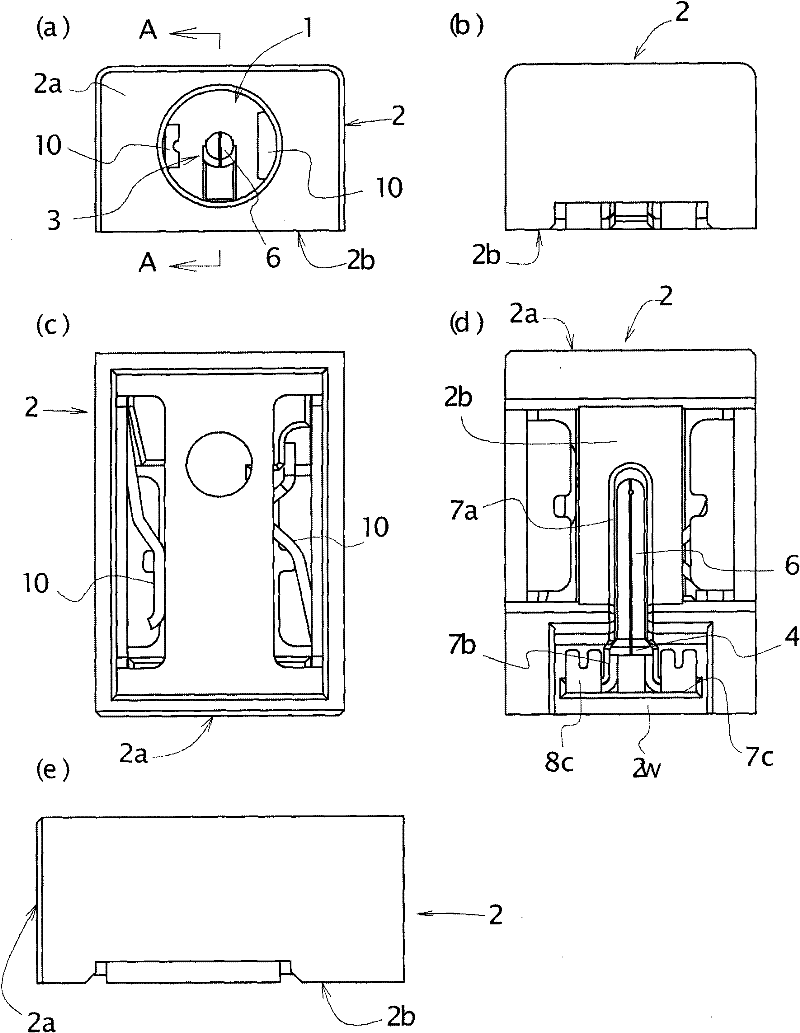
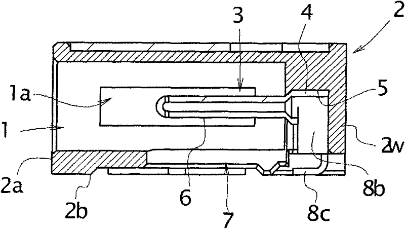
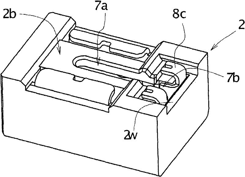
[0027] The embodiment of the power socket, such as Figure 1-Figure 3 As shown, it basically includes a housing 2, an installation space 5, a pin insertion port 7, and a pin plug 3; the housing 2 has a plug insertion hole 1 opened on the front 2a; The root 4 of the pin plug 3 at the rear end of the plug insertion hole 1 rear end of 2; the pin loading opening 7 is used to pack the pin portion 6 of the configuration pin plug 3 into the rear part side in the plug insertion hole 1 respectively, to the installation space 5. Insert and configure the root 4 of the pin plug 3; the root 4 of the pin plug 3 is placed in the installation space 5, so that the pin 6 is in the rear portion of the plug insertion hole 1 along the axis. The state of the configuration.

[0028] The above-mentioned housing 2 in this embodiment, as figure 1 (a)- figure 1...


PUM


Abstract

The present invention relates to a power socket for reducing material cost and assembling time, realizing miniaturization and improving position and dimension stability of a terminal. The power socket is provided with the following components: a housing (2) which is provided with a plug insertion hole (1) that is open at a front surface (2a); a mounting space (5) which is used for loading a root (4) of a pin plug (3) that is composed through configuring behind a back end of the plug insertion hole; a pin loading opening (7) which is respectively used for loading a plug (6) of the configured pin plug (3) in a plug insertion hole and is provided with the root of the configured pin plug in the mounting space; and the pin plug which has the root that is in a state of being loaded in the mounting space and therefore the pin is in a state of being configured along an axis in the back part of the plug insertion hole. The pin loading opening (7) is an opening in a loading direction which is orthogonal with the plug insertion hole (1) and is open at the side of the bottom (2b) of the housing (2). The back end of the mounting space is additionally provided with a slit-shaped space for loading an extension part of a terminal of the pin plug.

Description

technical field [0001] The present invention relates to a power socket for receiving DC power in various small electronic devices such as mobile phones, and having a pin plug disposed in the center of a plug insertion hole. Background technique [0002] Have the known power socket of this pin plug and have, as Figure 8 (a)- Figure 8 As shown in (c), the pin plug 13 is loaded from the loading port 12 opened at the rear of the housing 11, the pin portion 14 is arranged at a position along the axis of the plug insertion hole 15, and its root 16 is fixed on the plug. It is inserted into the installation space 17 constituted by the rear portion of the rear end of the hole 15 . The pin plug 13 locks a lance 18 formed around the root portion 16 to a step portion 19 formed in the mounting space 17 to prevent it from falling off. [0003] In the power socket of this conventional example, along with the miniaturization of the device, the pin plug 13 is also miniaturized. As a resul...

Claims


Application Information

Patent Timeline
Patent Type & Authority Applications(China)
IPC IPC(8): H01R24/76H01R13/42H01R13/46
Inventor 冈村智仁
Owner SMK CO LTD
Why Eureka
Try Eureka