

Elevator device
A technology for elevators and monitoring devices, which can be used in transportation, packaging, elevators, etc., and can solve problems such as unrealistic and unrealistic conditions.
- Summary
- Abstract
- Description
- Claims
- Application Information
AI Technical Summary
Problems solved by technology
Method used
Image

Examples
Embodiment approach 1
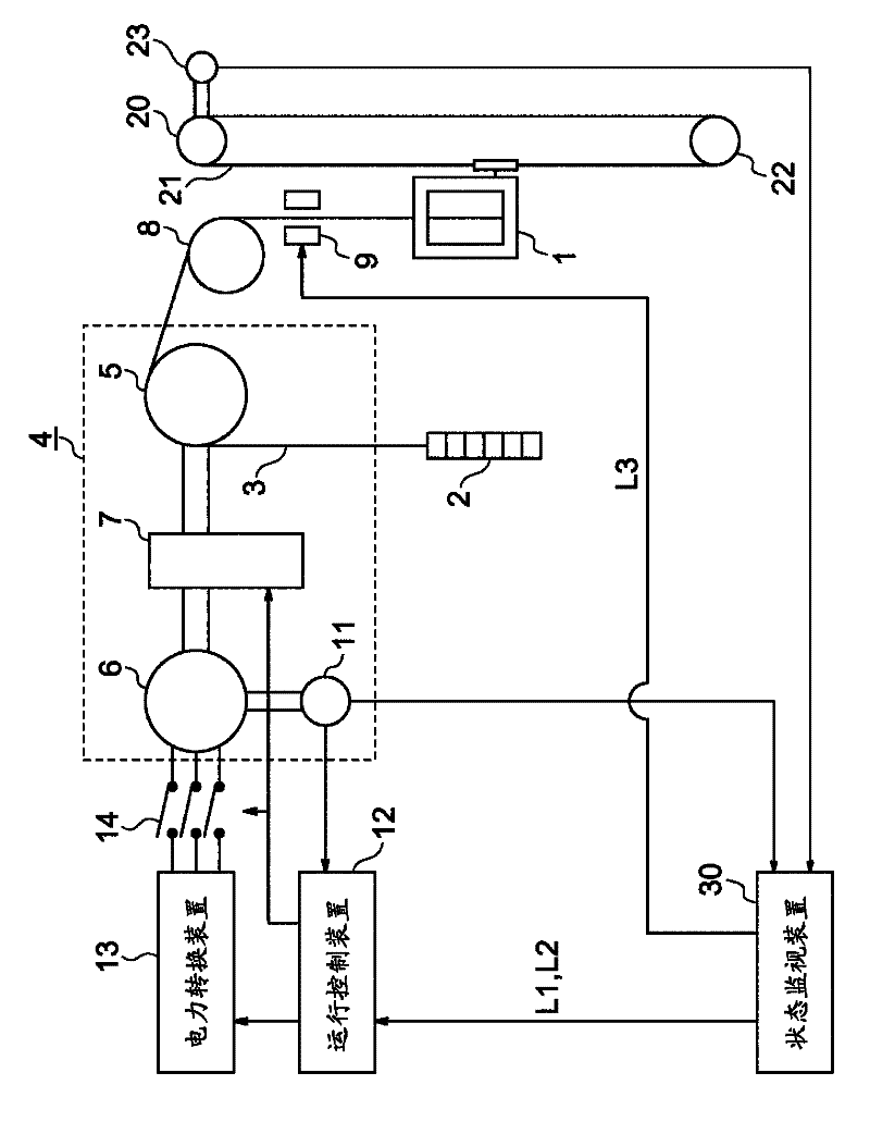
[0031] figure 1 It is a block diagram showing the elevator apparatus according to Embodiment 1 of the present invention. In the figure, the car 1 and the counterweight 2 are suspended in the hoistway by a plurality of main ropes 3 as suspension bodies, and are raised and lowered in the hoistway by the driving force of the traction machine 4 . The suspended body can adopt multiple conveyor belts. A plurality of guide rails (not shown) for guiding the lifting and lowering of the car 1 and the counterweight 2 are provided in the hoistway.
[0032] The hoisting machine 4 has a driving sheave 5 around which the main rope 3 is wound, a motor 6 that rotates the driving sheave 5 , and a hoisting machine brake 7 that brakes the rotation of the driving sheave 5 .
[0033] The traction machine brake 7 is, for example, an electromagnetic brake device. In the electromagnetic braking device, the brake shoe is pressed against the braking surface by the elastic force of the brake spring, ...
Embodiment approach 2
[0070] under, Figure 6 It is a configuration diagram showing an elevator apparatus according to Embodiment 2 of the present invention. In the figure, the hoisting machine brake 7 is provided with a brake switch 45 as a braking detection means (third detection means) for detecting operation / non-operation of the hoisting machine brake 7 . The brake switch 45 is a switch for determining the operation / non-operation of the hoisting machine brake 7 based on the movement of the movable part in the hoisting machine brake 7 . Furthermore, the brake switch 45 outputs an ON signal when the hoisting machine brake 7 is in an operating state (braking state), and outputs an OFF signal when it is in a non-operating state (released state).
[0071] The output signals of the motor encoder 11 and the brake switch 45 are input to the state monitoring device 40 . The state monitoring device 40 monitors a decrease in the braking capability of the hoisting machine brake 7 based on the output sign...
Embodiment approach 3
[0087] under, Figure 9 It is a configuration diagram showing an elevator apparatus according to Embodiment 3 of the present invention. In the drawing, an upper position display panel (upper mark) 56 is provided at the upper part in the hoistway. The upper position display panel 56 is normally secured in the topmost flat position. A lower position display board (lower mark) 57 is provided at the lower part in the hoistway. The lower position display panel 57 is usually fixed in the lowest level position.
[0088] A position sensor 55 is installed in the car 1 . The position sensor 55 detects that the car 1 is located at the topmost floor or the bottommost leveling floor position by detecting the position display boards 56 and 57 . The inspection section detection unit is composed of a position sensor 55, an upper position display panel 56 and a lower position display panel 57, and detects that the car 1 is moving in a pre-set inspection section in the hoistway.
[0089] I...
PUM
 Abstract
Description
Claims
Application Information