Fluid cooling system of a combustion engine charged by a turbocharger and method for cooling a turbine housing of a turbocharger

A technology of liquid cooling and turbine cover, applied in liquid cooling, engine cooling, coolant flow control, etc., can solve the problem of no coolant input and output design, and achieve the effect of reducing heat load and fuel consumption

Inactive Publication Date: 2011-07-27
GM GLOBAL TECH OPERATIONS LLC
View PDF1 Cites 16 Cited by
  • Summary
  • Abstract
  • Description
  • Claims
  • Application Information

AI Technical Summary

Problems solved by technology

However, there is no solution designe

Method used


Image

  • Fluid cooling system of a combustion engine charged by a turbocharger and method for cooling a turbine housing of a turbocharger
  • Fluid cooling system of a combustion engine charged by a turbocharger and method for cooling a turbine housing of a turbocharger
  • Fluid cooling system of a combustion engine charged by a turbocharger and method for cooling a turbine housing of a turbocharger

Examples


Example Embodiment

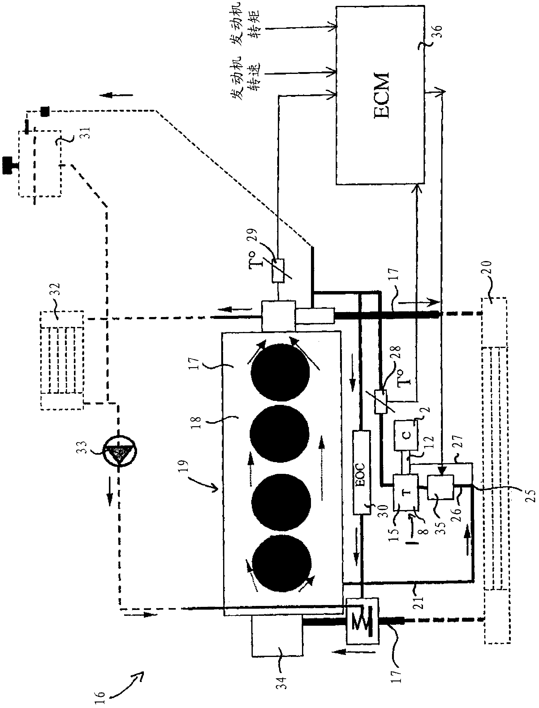
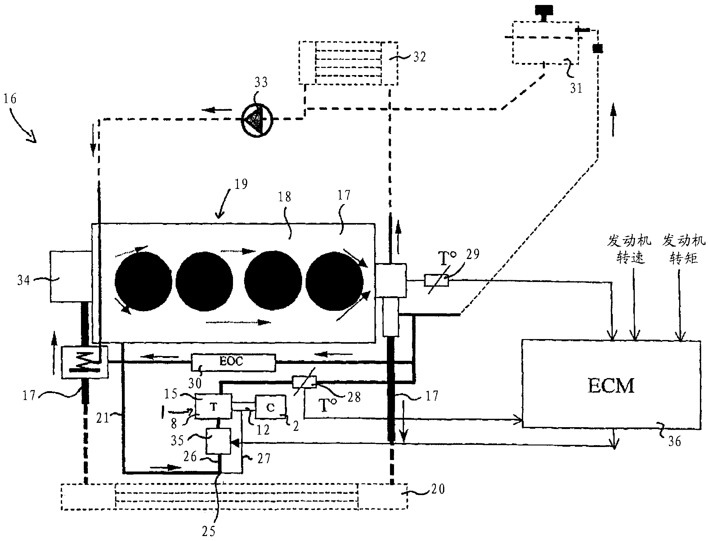
[0028] The same parts are provided with the same reference signs in both figures.

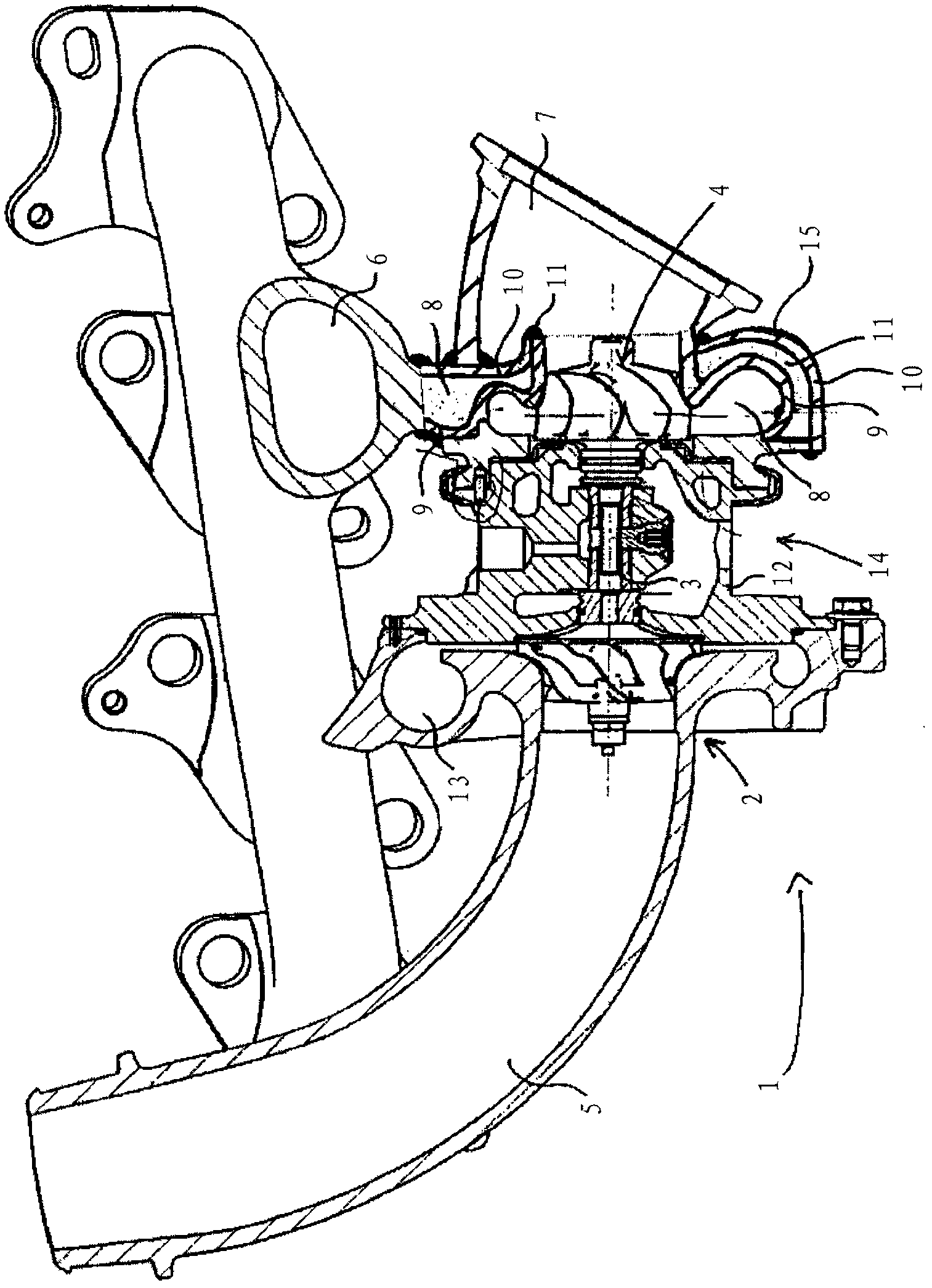
[0029] press figure 1 The turbocharger 1 has a compressor 2, a turbine 4, and a shaft 3 connecting the compressor 2 and the turbine 4. The shaft 3 is supported in a turbine bearing housing 12 by a turbine bearing 14.

[0030] The fresh air input through the air inlet 5 is compressed in the compressor 2 and output through the air outlet 13 and can be used in the intake passage of the internal combustion engine. The energy of the exhaust gas entering the turbine 4 through the exhaust gas inlet 6 is used to operate the compressor, in which the pressure of the exhaust gas drops, and the turbine causes the exhaust gas to exit through the exhaust gas outlet 7 again.

[0031] In operation, the turbine cover 15 is strongly heated by the hot exhaust gas. The turbine cover 15 is configured as a double wall having an inner wall 9 and an outer wall 10, wherein a cooling jacket 8 in which a coolant, such as wate...


PUM


Abstract

A fluid cooling system (16) of a combustion engine charged by a turbocharger (1) includes, but is not limited to a first cooling circuit (17) operable by a coolant pump (34) which runs through an engine block cooling jacket (18) and a second cooling circuit (21) branched off from the first cooling circuit, which runs through a cooling jacket (8) formed between an inner wall (9) and an outer wall (10) of a double-walled turbine housing of the turbocharger.

Description

technical field [0001] The invention relates to a liquid cooling system of an internal combustion engine, in particular of a motor vehicle, whose intake air is charged by a turbocharger. Furthermore, it also relates to a method for cooling a turbine housing of a turbocharger. Background technique [0002] Internal combustion engines, especially gasoline and diesel engines, have complex liquid cooling systems that have different demands under various operating conditions. For example during full load operation the engine block should be effectively cooled, however during cold starts it is desirable to transfer heat to the engine block in order to reduce fuel consumption. In addition to the engine block, other components such as the turbine bearing housing of the turbocharger are also cooled. [0003] From US Pat. No. 6,553,762 B2 it is known that the turbocharger has a double-walled design and is cooled by means of a coolant. However, there is no provision for the input an...

Claims


Application Information

Patent Timeline
IPC IPC(8): F01P3/02F01P3/12F01P7/16F01D25/14F02B39/00
CPCF05D2260/232F01P7/165F02B39/005F01D25/28F05D2220/40F01D25/14F01P2060/12F01D25/26F01P3/12F02C6/12
Inventor 赫尔穆特·赫斯勒
Owner GM GLOBAL TECH OPERATIONS LLC
Why Eureka
Try Eureka