Device for winding watches, in particular self-winding watches

A winding and automatic technology, applied in the field of mechanical watches, can solve the problems of affecting the efficiency of winding, limiting the degree of swing, not allowing programming and controlling the number of rotations and swings, etc.

Inactive Publication Date: 2011-07-27
MCM MILANO
View PDF5 Cites 6 Cited by
  • Summary
  • Abstract
  • Description
  • Claims
  • Application Information

AI Technical Summary

Problems solved by technology

[0018] Furthermore, in the case of watches with an oscillating movement along two axes, there is a limit to the degree of oscillation achievable while ensuring smooth movement, and this may affect the effici

Method used


Image

  • Device for winding watches, in particular self-winding watches
  • Device for winding watches, in particular self-winding watches
  • Device for winding watches, in particular self-winding watches

Examples


Embodiment Construction

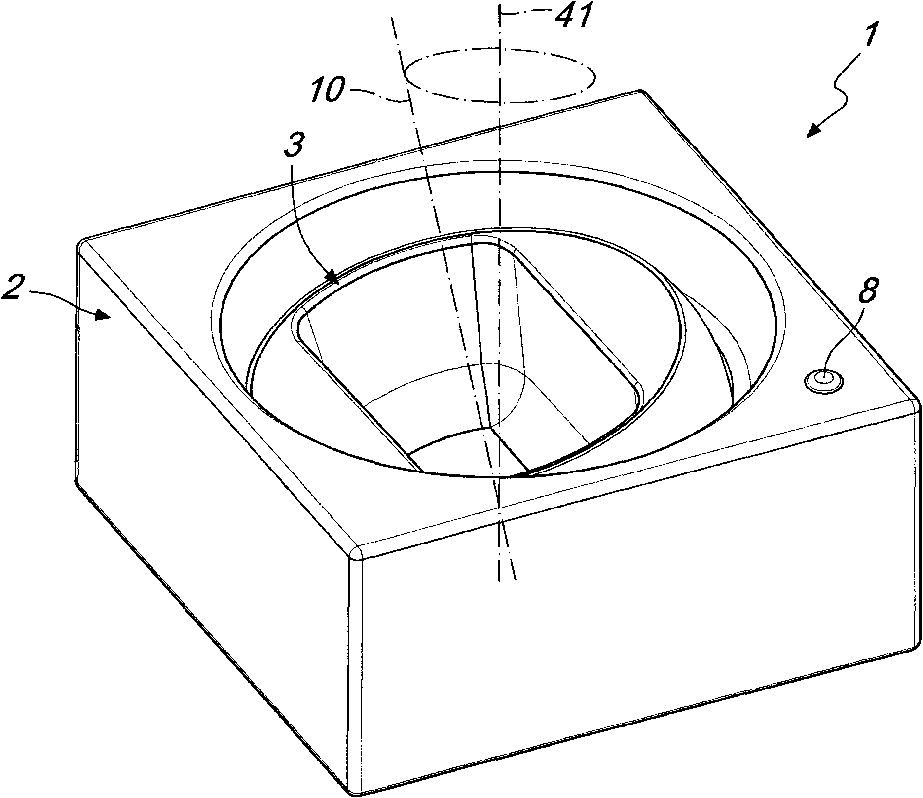
[0032] With reference to the figures, a device for winding a watch, in particular a self-winding watch, according to the invention is indicated generally by the reference numeral 1 and comprises a support structure 2 provided with a device suitable for accommodating the desired Seat 3 of the case of the wind-up watch.

[0033] Preferably, the support structure 2 has the shape of a parallelepiped, with seats 3 provided on its upper surface.

[0034] The support structure 2 can in any case have different shapes and dimensions, depending on the application requirements. Furthermore, the support structure 2 can in turn be housed in containers such as boxes and furnishing accessories.

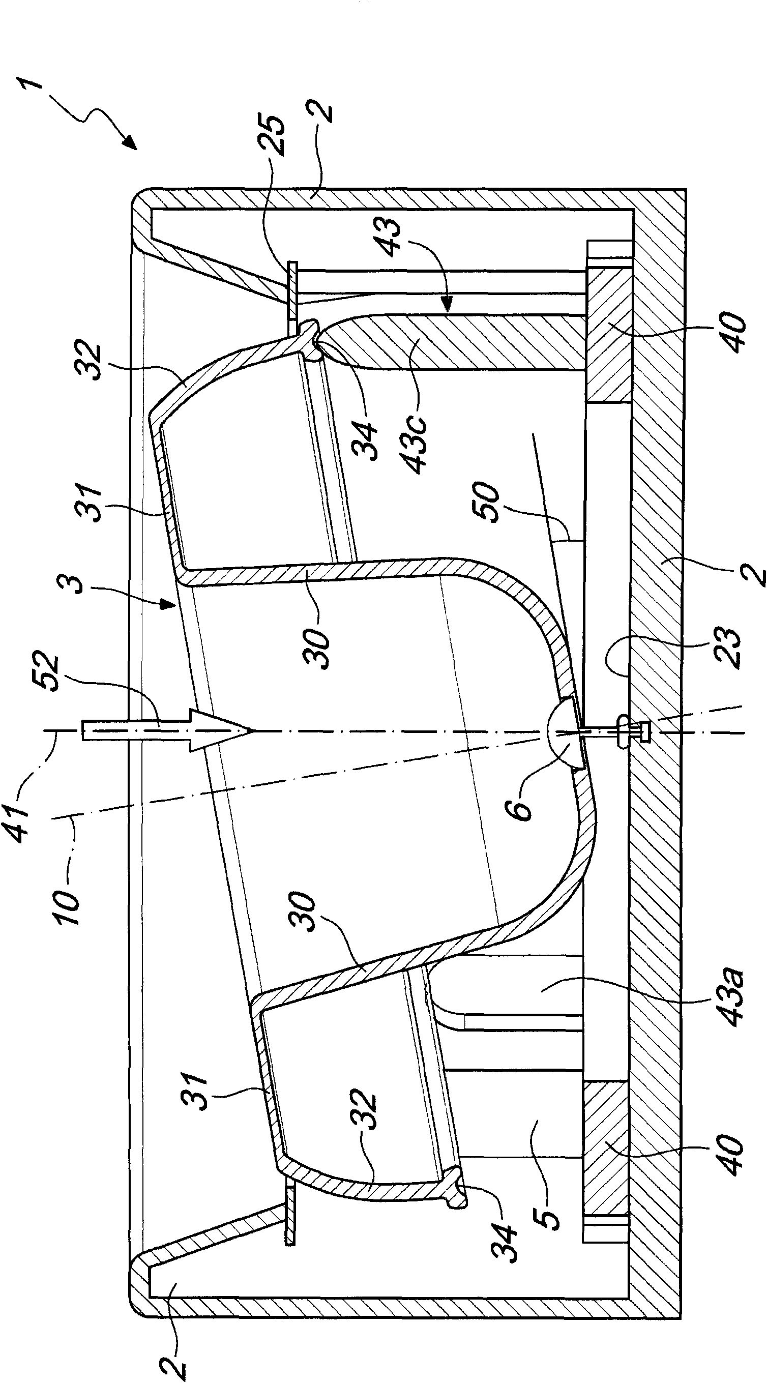
[0035] On the upper surface of the support structure 2 there is a circular hole in which is inserted the housing 3 of the watch to be wound.

[0036] This seat 3 has a shape suitable to stably accommodate the watch to be wound and may advantageously include structures for locking the watch thereon...


PUM


Abstract

A device for winding watches, particularly self-winding watches, comprises a supporting structure (2) provided with a seat (3) for accommodating the watch to be wound. The seat (3) is connected to transmission means (4) operated by a motor (5) and is inclined with respect to an axis (41) that is jointly connected to the supporting structure (2). The seat (3) can oscillate in a substantially conical manner about the axis (41) jointly connected to the supporting structure.

Description

technical field [0001] The invention relates to a device for winding mechanical watches, in particular self-winding mechanical watches, wrist watches and pocket watches. Background technique [0002] The term "self-winding watch" refers to a type of watch, usually a wristwatch, that has the property of being wound by the arm movement of its owner, so that the user does not have to wind the crown manually. [0003] Self-winding is enabled by a winding block called a rotor, which pivots due to the movement of the user's arm. This rotor is connected to a winding mechanism inside the watch, which includes a spring. The rotation of the rotor winds the spring which, by releasing itself, releases the energy required to move the hands and thus run the watch. [0004] The winding mechanism within a watch operates by changing the orientation of the rotor relative to an axis perpendicular to the ground and generally oriented in the direction of gravity. [0005] In order to wind the...

Claims


Application Information

Patent Timeline
IPC IPC(8): G04B3/00
CPCG04B5/00G04D7/009
Inventor A・莫罗尼M・莫罗尼F・塞络罗
Owner MCM MILANO
Why Eureka
Try Eureka