Heavy loading shaft push device for hole

A heavy-duty, hole-use technology, applied to mechanical equipment, connecting components, etc., can solve the problems of bolts being prone to partial load, low design safety factor, bolt overload, etc., and achieve small design limitations, large safety factor, axial load high effect

Active Publication Date: 2012-10-03
HANGZHOU ADVANCE GEARBOX GRP
View PDF6 Cites 0 Cited by
  • Summary
  • Abstract
  • Description
  • Claims
  • Application Information

AI Technical Summary

Problems solved by technology

[0005] The working principle of the end pressure plate bolt bearing thrust is: the thrust shaft 12 generates an axial force P, passes through the thrust plate 13, and then transmits the force to the thrust bolt 16 on the shaft end pressure plate 15; the bolt 16 bears the axial force, Due to the limitation of installation space, the size and quantity of bolts 16 will be limited, so the design safety factor is lower than that of the circlip for holes; at the same time, bolts are easily affected by partial loads, resulting in overloading of a single bolt until failure

Method used


Image

  • Heavy loading shaft push device for hole
  • Heavy loading shaft push device for hole
  • Heavy loading shaft push device for hole

Examples


Embodiment Construction

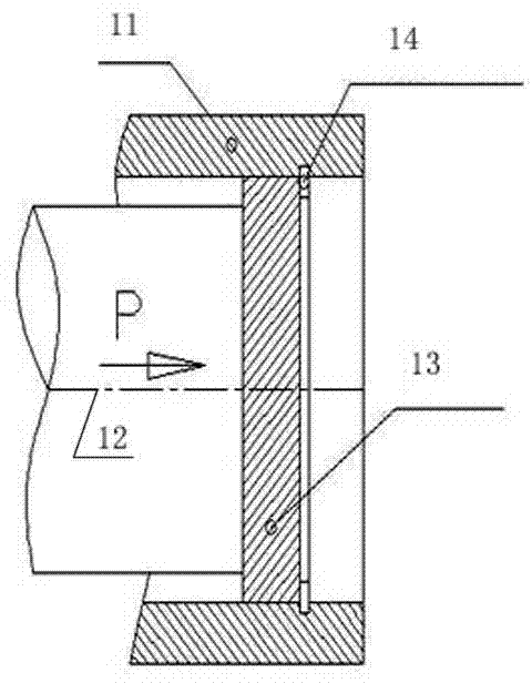
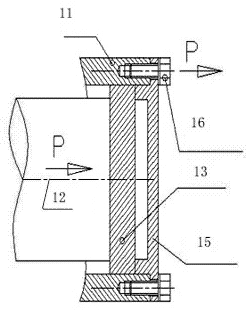
[0018] The present invention will be described in detail below in conjunction with accompanying drawing: image 3 , 4 As shown, the present invention includes a thrust shaft 22 placed in the outer shaft 21, and a thrust plate 23 fixed on the inner wall of the outer shaft 21 is arranged at the shaft end of the thrust shaft 22 radially (axially). At least two shear plates 25 radially embedded in the grooves 24 of the inner wall of the outer shaft 21 are disposed on the outside of the push plate 23 , and the shear plates 25 are fixedly connected to the push plate 23 by bolts 26 .

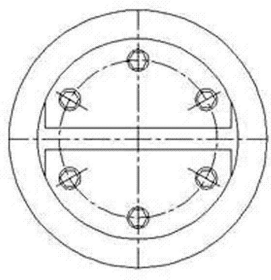
[0019] The shear plate 23 has two left and right pieces symmetrically embedded in the ring groove 24 of the inner wall of the corresponding outer shaft 21; the bolts 26 are evenly distributed on the outer side of the shear plate 25 according to the circumference It is fixedly connected with thrust plate 23.

[0020] The structural principle of the present invention is: the thrust shaft 22 generat...


PUM


Abstract

The invention discloses a heavy loading shaft push device for a hole. The device comprises a push shaft which is arranged in an outer shaft; a bearing push plate which is fixed on the inner wall of the outer shaft is radially (axially) arranged on the shaft end of the push shaft; at least two shearing push plates which are radially embedded into a groove of the inner wall of the outer shaft are arranged on the outer side of the bearing push plate, and the shearing push plates are fixedly connected with the bearing push plate through bolts; a left shearing push plate and a right shearing push plate are symmetrically and radially embedded into an annular groove of the corresponding inner wall of the outer shaft; and the bolts are uniformly and circumferentially distributed on the outer sides of the shearing push plates and connect the shearing push plates and the bearing push plate. The heavy loading shaft push device has the characteristics of small design limitation and huge bearing and the like, and is easy to process and assemble and works reliably.

Description

technical field [0001] The invention relates to an axial propulsion device capable of bearing huge axial loads, in particular, it is applicable to mechanical equipment with heavy loads and very high reliability requirements, such as ships, metallurgy, wind power and other industries. Background technique [0002] The traditional axial bearing methods mainly include the following two types: the first one is the bearing bearing of the retaining ring for the hole, see figure 1 As shown, it includes a thrust shaft 12 placed in the outer shaft 11, a thrust plate 13 radially arranged in the outer shaft 11 is arranged at the axial end of the thrust shaft 12, and a hole is adopted on the outside of the thrust plate 13 It is fixed on the inner wall of the outer shaft 11 with a circlip 14 . [0003] The working principle of the above-mentioned circlip bearing for the hole is: the thrust shaft 12 generates an axial force P, passes through the thrust plate 13, and then transmits the ...

Claims


Application Information

Patent Timeline
Patent Type & Authority Patents(China)
IPC IPC(8): F16B21/16
Inventor 汤克平汪长青
Owner HANGZHOU ADVANCE GEARBOX GRP
Why Eureka
Try Eureka