Unlock instant, AI-driven research and patent intelligence for your innovation.

Liquid crystal display device

A technology of liquid crystal display and display area, which is applied in the direction of instruments, nonlinear optics, optics, etc., and can solve the problems of liquid crystal leakage, insufficient expansion of liquid crystal, and generation of bubbles, etc.

Active Publication Date: 2011-08-03
JAPAN DISPLAY INC
View PDF5 Cites 5 Cited by
  • Summary
  • Abstract
  • Description
  • Claims
  • Application Information

AI Technical Summary

Problems solved by technology

Therefore, there is a problem that the liquid crystal finally passes through the sealing member, causing leakage of the liquid crystal.
[0004] On the other hand, the corner portion of the sealing member is relatively far from the center portion of the liquid crystal display compared to the side portion of the sealing member in the liquid crystal display, and thus, the liquid crystal material is insufficient in the corner portion, and the liquid crystal cannot sufficiently expand to corner
Therefore, there is a problem that air bubbles are generated in the portion where the amount of liquid crystal is insufficient

Method used


Image

  • Liquid crystal display device
  • Liquid crystal display device
  • Liquid crystal display device

Examples


Embodiment 1

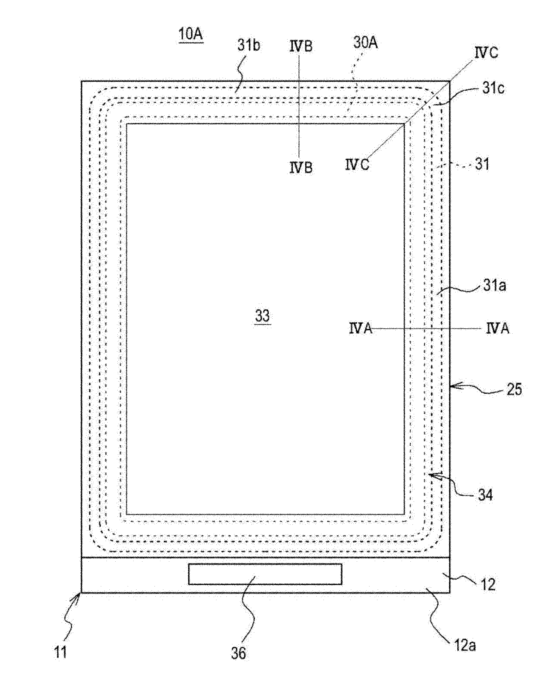
[0056] First, refer to figure 1 The configuration of a liquid crystal display 10A according to Embodiment 1 is described. Such as figure 1 As shown, in the liquid crystal display 10A of Embodiment 1, the array substrate 11 (which corresponds to "one substrate" according to the embodiment of the present invention) and the color filter substrate 25 (which corresponds to "the other substrate" according to the embodiment of the present invention) substrates") are arranged to face each other, and various wirings etc. are formed on the first transparent substrate 12 formed of rectangular glass etc. in the array substrate 11, and color filter layers etc. are formed on the first transparent substrate 12 formed of rectangular glass etc. on the second transparent substrate 26 formed of glass or the like. Then, the array substrate 11 and the color filter substrate 25 are bonded together by the sealing member 31, and the liquid crystal 35 (see image 3 ) is enclosed in the space formed...

Embodiment 2

[0075] Next, refer to Figures 6A to 6C A liquid crystal display 10B according to Embodiment 2 is described. The liquid crystal display 10B according to Embodiment 2 differs from the liquid crystal display 10A according to Embodiment 1 only in the formation pattern of the cell thick region 30B. Thus, the same reference numerals designate the same configuration as that of the liquid crystal display 10A according to Embodiment 1, and a detailed description thereof will be omitted.

[0076] In the liquid crystal display 10B of Embodiment 2, as Figures 6A to 6C As shown, the unit thick region 30B1 is formed to have a wider width WB1 on the side of the long side portion 31a of the sealing member, while the width WB2 of the unit thick region 30B2 is formed to be narrower on the side of the short side portion 31b of the sealing member.

[0077] As described above, the liquid crystal 35 quickly reaches the sides of the sealing member 31 . Specifically, however, the long side porti...

Embodiment 3

[0079] Next, refer to Figures 7A to 7C A liquid crystal display 10C according to Embodiment 3 is described. The liquid crystal display 10C according to Embodiment 3 differs from the liquid crystal display 10A according to Embodiment 1 only in the formation pattern of the cell thick region. Therefore, the same reference numerals designate the same configuration as that of the liquid crystal display 10A according to Embodiment 1, and a detailed description thereof will be omitted.

[0080] Such as Figures 7A to 7C As shown, in the liquid crystal display 10C of Embodiment 3, the cell thick region 30C is formed only in the side portions 31a and 31b of the sealing member 31 formed on the array substrate 11 except the corner portion 31c.

[0081] By employing such a structure, according to the liquid crystal display 10C of Embodiment 3, the cell thick region 30C is formed only in the side portions 31 a and 31 b of the sealing member 31 where embedding of the liquid crystal 35 ea...


PUM


Abstract

The present invention provides a liquid crystal display device, including: a pair of substrates that are bonded together with a sealing member having a closed loop shape that is formed around a display region with a space maintained from the display region; and a liquid crystal layer that is disposed between the pair of substrates so as to maintain a cell gap of a predetermined thickness, wherein, between the display region and the sealing member, a cell thick area, in which a cell gap larger than the cell gap of the display region is formed, is formed.

Description

technical field [0001] The present invention relates to a liquid crystal display manufactured by a liquid crystal drop (one drop fill) (hereinafter referred to as "ODF") method, and more specifically, to a liquid crystal display that suppresses embedding of liquid crystal in a sealing member and suppresses generation of air bubbles in the liquid crystal. Background technique [0002] The ODF method is a known method of encapsulating liquid crystals in liquid crystal displays. The ODF method is a method in which any one of two substrates such as an array substrate and a color filter substrate on which various wirings etc. The substrate on the side is coated with a closed-loop-shaped sealing member, liquid crystal is dropped into the inside of the sealing member, and then the substrate is covered and bonded to the other substrate on the upper side, and cured by ultraviolet light or heat. the sealing member. [0003] In the ODF method, a liquid crystal is injected into a coat...

Claims


Application Information

Patent Timeline
Patent Type & Authority Applications(China)
IPC IPC(8): G02F1/1339G02F1/1333
CPCG02F1/1339G02F1/133371G02F1/1341G02F1/13415G02F1/133388
Inventor 仓泽隼人
Owner JAPAN DISPLAY INC